


Sprache /
Language
:
Deutsch /
english
Montageanleitung
Installation Guide
Version:
1.2
5
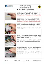
Schritt 5: In diesem Schritt werden die drei Phasen und der Neutralleiter an das Gerät
angeschlossen. Auf die Phasenfolge muss geachtet werden. Die Reihenfolge von links
nach rechts: L1, L2, L3. Bitte bei den folgenden Schritten den Anschlussplan im
Datenblatt beachten.
Step 5: In this step, the three phases and the neutral conductor are connected to the
device. The phase sequence must be respected. The sequence from left to right: L1, L2,
L3. Please see the connection diagram in the data sheet for the following steps.
6
Schritt 6: Anschließend werden alle drei Stromwandler, die für die Messung des Stromes
benötigt werden, auf die drei Zuleitungsadern nach dem Hauptzähler aufgeschnappt. Auf
richtig geschlossenen Kern achten!
Bitte den Montagehinweis auf der Unterseite des
Wandlers für die Montagerichtung beachten.
Ebenfalls muss beachtet werden, dass der
jeweilige Stromwandler auf der richtigen Phase sitzt. Stromwandler 1 auf L1,
Stromwandler 2 auf L2 und Stromwandler 3 auf L3. Das komplette Schaltbild finden Sie
im technischen Datenblatt.
Step 6: Then all three current transformers, which are needed for the measurement of
the current, are snapped on the three supply wires behind the main electric meter. The
core must be securely closed.
Please note the mounting information on the bottom of the
converter for the mounting direction.
Also, make sure that the respective current
transformers are placed on the right phase. Current transformer 1 on L1 current
transformer 2 on L2 and current transformers 3 on L3. For the complete circuit diagram,
please see the technical data sheet.
7
Schritt 7: Die drei Stromwandler müssen jetzt noch sekundärseitig angeschlossen
werden. Auch hier die Beschriftung auf der Unterseite der Stromwandler beachten und
nach Anschlussplan im Datenblatt am AD-PVO 2000 auflegen. Die beiden
Anschlussdrähte dürfen nicht verdreht und die Stromwandler untereinander nicht
vertauscht werden. Die Reihenfolge der Stromwandler entspricht der Phasenfolge.
Step 7: The three current transformers must now be connected even on the secondary
side. Again, note the lettering on the bottom of the current transformers and the
connection diagram in the data sheet. The two connection wires must not have reverse
polarity and the current transformers are not mutually interchanged. The sequence of the
current transformers corresponds to the sequence of the phase.
8
Schritt 8: Anschließen der Last am Lastrelais. Die Last, die am Lastrelais angeschlossen
wird, darf die im Datenblatt angegebenen Anschlussdaten nicht überschreiten. Es
handelt sich hier um einen potentialfreien Kontakt, daher muss die Phase extern heran
geführt werden. Bei stark induktiven oder kapazitiven Lasten wird empfohlen mit dem
Lastrelais einen externen Schütz anzusteuern. So wird der Kontaktverschleiß deutlich
reduziert.
Step 8: Connection of the load at the load-relay. The load which is connected to the load-
relay must not exceed the connection specifications in the data sheet. This is a potential
free contact, so the phase must be supplied externally. For heavy inductive or capacitive
loads it is recommended to drive an external contactor with the load-relay. This reduces
contact wear.
Erstellt: M. Alt
Freigegeben: H. Biehler
Seite: 2 von 3
Überarbeitungsstatus: 21.11.2013
AD-PVO 2000 / AD-PVO 6000


