


2.1
BOILER ROOM
2.1.1
ACCESSIBILITY
The boiler room must be large enough to allow good access to boiler.
The following minimum distances (mm) are required around the boiler:
- front
500
- sides
100
- rear 150
-
above
700
2.1.2
VENTILATION
The boiler room must be fitted with top and bottom vents according to
the table below or current regulations.
2.1.3
BASE
The base on which the boiler rests must be made of non-combustible
materials.
2.2
CONNECTION
2.2.1
CHIMNEY CONNECTION
The boiler can be connected to a suitable flue or to the chimney by a
metal pipe rising at an angle from the boiler to the chimney. It must be
easy to remove to give access to the flue pipes when servicing the boiler.
IMPORTANT
Boilers must be installed by a qualified engineer, in
accordance with the prevailing local standards and
regulations.
2.2.2
CENTRAL HEATING CONNECTION
2.2.2.1
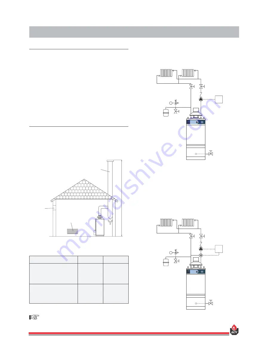
Examples of basic circuit configurations
The drain valve and safety valve must be connected to the waste
water system in accordance with current regulations.
1. 3-way manual motorisable mixer valve
2. Safety valve pre-set to 3 bar with pressure gauge
3. Circulator
4. Non-return valve
5. System filling valve
6. Expansion tank
7. Room thermostat
8. ACV 13 controller (see controller kit page 5)
9. Central heating isolating valve
10. Drain valve
Fig. 2: Configuration with circulator controlled
by a room thermostat
2
INSTALLATION
10
6
2
3
4
7
5
9
9
10
1
6
2
3
4
8
5
9
9
Fig. 3: Configuration with motor driven mixer valve
Fig. 1: Boiler room ventilation and chimney connection
A
B
D
C
A. Top vent
B. Bottom vent
C. Chimney height
D. Chimney diameter
3
ALFA G
ALFA GP
Ventilation
Min. fresh air requierement
m
3
/h
82,8
82,8
Top vent (A)
dm
2
1,5
1,5
Bottom vent (B)
dm
2
1,5
1,5
Chimney
C = 5 m Ø min. D
mm
130
130
C = 10 m Ø min. D
mm
130
130
C = 15 m Ø min. D
mm
130
130


