background image

16

I

I – 2 Milling Specific Oper

ations

Circle pattern

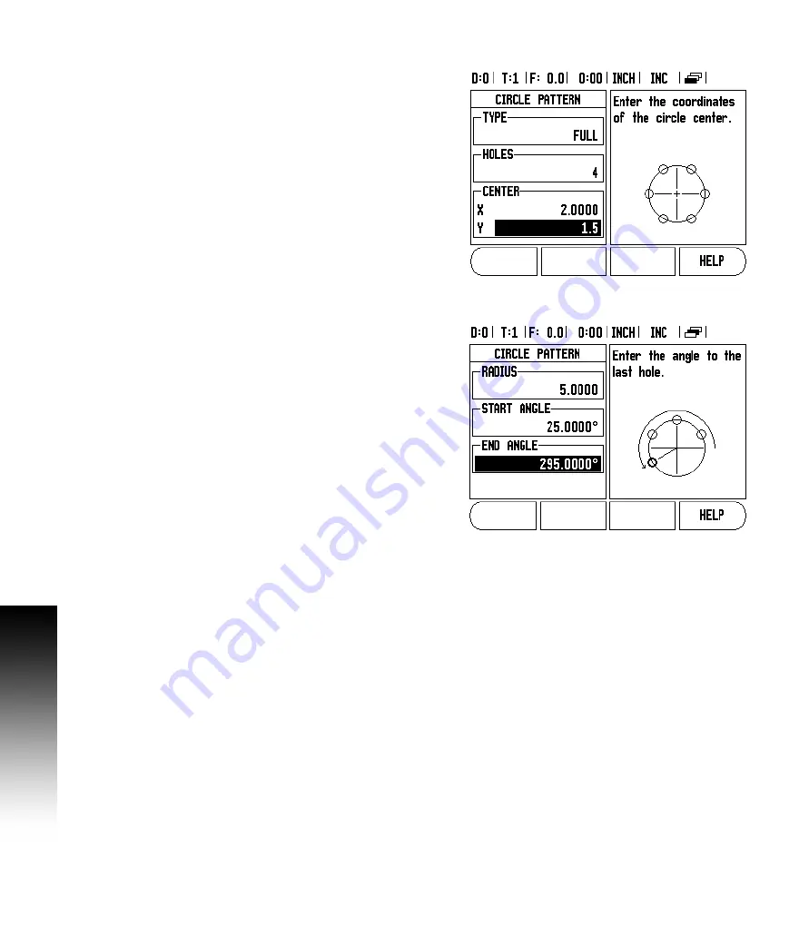
Example: Enter data, and  execute a circle pattern.

„

Holes (no. of): 4

„

Coordinates of center: X = 2.0” / Y = 1.5”

„

Bolt circle radius: 5

„

Start angle: Angle between X axis, and  first hole: 25°

„

Hole depth: Z = -0.25”

1st step: Enter data

U

Press CIRCLE PATTERN hard key.

U

Enter the type of circle pattern (full). Cursor to the next field.

U

Enter the number of holes (4).

U

Enter the X, and  Y coordinates of the circle center (X=2.0), (Y=1.5). 
Cursor to the next field.

U

Enter the radius of the circle pattern (5).

U

Enter the start angle (25°).

U

Enter the end angle (295°) (this can only be changed if entering a 
“segment”). The End Angle is defined as the angle from the positive 
X-axis to the end of the pattern. 

U

Enter the depth when needed. The depth of the hole is optional, and  
may be left blank. If not required, press ENTER.

U

Three views are available: Incremental DRO, Pattern Graphic, and 
Absolute DRO. Press the VIEW soft key to toggle through the 
available screens.

2nd step: Drill

U

Move to hole:

U

Traverse the X, and  Y axes until display value zero.

U

Drill:

U

Traverse to display value zero in the tool axis. After drilling, retract 
the drill in tool axis.

U

Press the NEXT HOLE soft key.

U

Continue to drill the remaining holes in the same way.

U

When the pattern is complete, press the END soft key.

Содержание VUE

Страница 1: ...VUE READOUTS REFERENCE MANUAL SALES SERVICE A Tech Authority Inc 13745 Stockton Ave Chino CA 91710 909 614 4522 sales atechauthority com ...

Страница 2: ......

Страница 3: ...so used to adjust the screen contrast 5 Axis Keys 6 Numeric Keypad 7 ENTER key 8 CLEAR key 9 Hard function keys 1 1 1 2 1 Page Indicator 2 Set Zero Indicator Soft Key function Soft key Opens on screen Help Instructions Toggles between Inch and Millimeter units see Units on page 5 This soft key toggles between radius and diameter displays This function is for Turning applications only see Diameter ...

Страница 4: ... the Tool Table See Tool Table on page 8 for Milling See Tool Table on page 22 for Turning The tool key is a soft key for the one axis readout only Opens the Datum form to set the datum for each axis See Datum Setting on page 10 for Milling See Datum Setting on page 24 for Turning The datum key is a soft key for the one axis readout only ...

Страница 5: ...meter Operations Refer to the Setup section also Begin by pressing the SETUP soft key Press the soft key INSTALLATION SETUP Press the access code numbers 8891 using the numeric key pad Press the ENTER key The readout is now ready for machine parameter setting operations IMPORTANT The access code is 8891 IMPORTANT Supervisors may wish to remove this page from the Reference Manual after initially se...

Страница 6: ...vi Readout Parameter Access Code ...

Страница 7: ... keys SETUP soft key Hard keys ENTER hard key This User s Manual covers the functions of the VUE for both milling and turning applications Operational information is arranged in three sections General Operations Mill Specific Operations and Turn Specific Operations The VUE DRO is available in one two and three axis form The 3 axis VUE DRO is used through out this manual for illustration and descri...

Страница 8: ...viii VUE Fonts ...

Страница 9: ...e 1 year at no charge Notice of the claimed defect must be received by ACU RITE within the warranty period This warranty applies only to products and accessories installed and operated in accordance with this reference manual ACU RITE shall have no obligation with respect to any defect or other condition caused in whole or part by the customer s incorrect use improper maintenance modification of t...

Страница 10: ...x ...

Страница 11: ...ls within Notes vii VUE Fonts vii Hassle Free Warranty Warranty ix I 1 Introduction to VUE Layout of Screen 1 VUE Hard Keys 2 Operating Modes 3 Reference Mark Evaluation 3 Working without reference mark evaluation 4 ENABLE DISABLE REF function 4 Job Setup Parameters 5 Units 5 Scale Factor 5 Mirror 5 Diameter Axes 6 Near Zero Warning 6 Status Bar Settings 6 Job Clock 6 Console Adjustment 7 Language...

Страница 12: ...stance Preset 14 1 2 Hard Key 15 Circle and Linear Pattern 15 Functions for milling pattern soft keys 15 Circle pattern 16 Linear Pattern 17 Incline Arc Milling 17 Incline Milling 18 Arc Milling 20 I 3 Turning Specific Operations Tool Table 22 Tool Display Icon 22 Setting Tool Offsets with Tool Set 22 Setting Tool Offsets with Lock Axis Function 23 Calling a Tool from the Tool Table 23 Datum Setti...

Страница 13: ...rting a Non linear Error Compensation Table 33 Configuring the Compensation Table 33 Reading the Graph 33 Viewing the Compensation Table 34 Exporting the Current Compensation Table 34 Importing a New Compensation Table 34 Backlash Compensation 34 Counter Settings 35 Diagnostics 35 Keypad Test 35 Display Test 35 II 2 Installation and Electrical Connections Installation 36 Electrical requirements 36...

Страница 14: ...xiv ...

Страница 15: ...ng up the Status Bar parameters Display Area Indicates the current position of each axis Also shows forms fields instruction boxes error messages and help topics Axis Labels Indicates axis for corresponding axis key Ref Symbols Indicates current reference mark status Soft key Labels Indicates the various milling or turning functions 1 Datum 2 Tool 3 Feed Rate 4 Job Clock 5 Unit of Measure 6 Operat...

Страница 16: ...page 15 The CALC hard key opens the Calculator functions for standard math trigonometry RPM and Taper Turning only functions see page 26 The DATUM hard key opens the Datum form to set the datum for each axis for Milling see page 10 for Turning see page 24 The TOOL hard key opens the Tool Table for Milling see page 8 for Turning see page 22 The CIRCLE PATTERN hard key Mill only opens the Circle Pat...

Страница 17: ...e to calculate the amount of distance to go required to get to the desired nominal position relative to the edge of the tool that will be doing the cutting If the VUE is configured for turning all tool offsets are used in both the absolute and incremental modes U Press the ABS INC hard key to toggle between these two modes To view other soft key functions in either absolute or incremental mode use...

Страница 18: ...his is important when using encoders with Fixed Reference Marks instead of ones with Position Trac feature When the DISABLE REF soft key is pressed the recovery routine is paused and any reference marks that are crossed during encoder movement are ignored When the ENABLE REF soft key is then pressed the recovery routine once again becomes active and the next crossed reference mark will be selected...

Страница 19: ... to scale the part up or down A scale factor of 1 0 creates a part with the exact size as dimensioned on the print A scale factor 1 grows the part and 1 shrinks the part U The numeric keys are used to enter a number greater than zero The number range is 0 1000 to 10 000 A negative value may also be entered U The scale factor settings will be retained on a power cycle U When the scale factor is a v...

Страница 20: ...oft key to enable or simply begin entering values using the numeric keys The current position box will begin moving when the position is within range Status Bar Settings The Status Bar is the segmented bar at the top of the screen which displays current datum tool feed rate job clock and page indicator U Press the ON OFF soft key for each setting to be displayed Job Clock The job clock shows the h...

Страница 21: ...s can be imported or exported over the Regular Type B USB port U Press the IMPORT EXPORT soft key in the Setup screen U Press IMPORT to download operating parameters from a PC U Press EXPORT to upload the current operating parameters to a PC U To exit press the C key Set Zero Soft Key The SET ZERO soft key is a key that determines the effect of pressing an Axis key This key is a toggle key switchi...

Страница 22: ...on VUE has tool compensation This allows workpiece dimensions to be entered directly from the drawing The displayed distance to go is then automatically lengthened R or shortened R by the value of the tool radius for more information see Presets on page 12 The length offset may be entered as a known value or the VUE may determine the offset automatically The tool length is the difference in length...

Страница 23: ...ength of each tool Move the tool until its tip is touching the reference surface Press the TEACH LENGTH soft key The VUE will calculate an offset relative to this surface Repeat the procedure for each additional tool using the same reference surface Calling the Tool from the Tool Table U To call a tool press the TOOL hard key U Use the UP DOWN arrow keys to Cursor through the selection of tools 1 ...

Страница 24: ...nships between the axis positions and the display values Setting datum points can be done by using the VUE probing functions with a tool Datum points are set by touching the edges of the workpiece one after the other with a tool and manually entering the tool positions as datum points ...

Страница 25: ...he C key Example Probe workpiece edge and set edge as datum U Preparation Set the active tool to the tool that will be used to set the datum Datum axis X 0 Tool diameter D 0 25 U Press DATUM hard key U Press the DOWN arrow key until the X axis field is highlighted U Press PROBE soft key U Press EDGE soft key U Touch workpiece edge U Press the TEACH soft key to store the current absolute value whil...

Страница 26: ...erator to indicate which side of the tool will be doing the machining at the nominal position The R soft key in the Preset form defines the offset that will be in effect during the move R indicates that the center line of the current tool is in a more positive direction than the edge of the tool R indicates that the center line is in a more negative direction than the edge of the current tool Usin...

Страница 27: ...to axis form U Press ENTER U Traverse the Y axis until the display value is zero The square in the near zero warning is now centered between the two triangular marks U Press the SET ZERO soft key so that the DRO is still in Set mode U Press the X axis key U Enter nominal position value for corner point 2 X 1 5 select tool radius compensation R with R soft key Press twice until R is shown next to a...

Страница 28: ...NTER hard key U Drill hole 1 Traverse the X Y and Z axis until the display value is zero The square in the near zero warning is now centered between the two triangular marks Retract the drill To preset the location for Hole 2 U Press the X axis key U Enter nominal position value for hole 2 X 1 5 mark the input as an incremental dimension press the I soft key U Press the Y axis key U Enter nominal ...

Страница 29: ...cribes the hole pattern functions for Circle and Linear patterns Press the CIRCLE PATTERN or LINEAR PATTERN hard key to access the Pattern function then enter the required data VUE then calculates the positions of all the holes and displays the pattern graphically on the screen The View Graphic enables verification of the hole pattern before any machining starts It is also useful when selecting ho...

Страница 30: ... U Enter the end angle 295 this can only be changed if entering a segment The End Angle is defined as the angle from the positive X axis to the end of the pattern U Enter the depth when needed The depth of the hole is optional and may be left blank If not required press ENTER U Three views are available Incremental DRO Pattern Graphic and Absolute DRO Press the VIEW soft key to toggle through the ...

Страница 31: ...ing the spacing between each row of the pattern Information entry and operation of the Linear Pattern feature is very similar to the Hole Pattern feature described earlier Incline Arc Milling The incline and arc milling features provide ways to machine a flat diagonal surface incline milling or a rounded surface arc milling using a manual machine The following soft keys are also available while in...

Страница 32: ...U Press C to exit the form without executing Settings are retained until power is turned off Executing the Incline Milling feature U Execute the milling operation by opening the entry form and pressing the RUN soft key or enter key The screen switches to the incremental DRO view U Initially the DRO shows the current incremental moving distance from the start point Move to the start point and make ...

Страница 33: ...presenting the surface the tool is in position The tool crosshair remains fixed in the center of the graph As the table is moved the surface line moves U Press the END soft key to exit the milling operation Tool radius compensation is applied based on the radius of the current tool If the plane selection involves the tool axis the tool tip is assumed to have a ball end The tool offset direction R ...

Страница 34: ... operation U Press C to exit the form without executing Settings are retained until power is turned off Executing the Arc Milling feature U Execute the milling operation by opening the entry form and pressing the RUN soft key or ENTER key The screen switches to the incremental DRO view U Initially the DRO shows the current incremental distance from the start point Move to the start point and make ...

Страница 35: ...epresenting the surface the tool is in position The tool crosshair remains fixed in the center of the graph As the table is moved the surface line moves U Press the END soft key to exit the milling operation Tool radius compensation is applied based on the radius of the current tool If the plane selection involves the tool axis the too tip is assumed to have a ball end The tool offset direction R ...

Страница 36: ...con The icon is used to indicate that the displayed value is a diameter value No icon visible indicates that the display is a radius value Setting Tool Offsets with Tool Set Example 1 Using Tool Set The Tool Set operation can be used to set a tool s offset using a tool when the diameter of the workpiece is known U Touch the known diameter in the X axis 1 U Press the TOOL hard key U Scroll to the d...

Страница 37: ...IS function U Press the TOOL hard key U Select tool and press ENTER U Press the X axis key U Turn a diameter in the X axis U Press the LOCK AXIS soft key while the tool is still cutting U Retract from the current position U Turn the spindle off and measure the workpiece diameter U Enter the measured diameter or radius and press ENTER Remember to ensure the VUE is in diameter display mode Ø Calling...

Страница 38: ...dimension as the value that the display should be showing Example Setting a workpiece datum U Call the tool data by selecting the tool which being used to touch the workpiece U Press the DATUM hard key The Cursor will be in the Datum Number field U Enter the datum number and press the DOWN ARROW key to go to the X axis field U Touch the workpiece at point 1 U Enter the radius or diameter of the wo...

Страница 39: ...ck Axis function U Press the DATUM hard key The Cursor will be in the Datum Number field U Enter the datum number and press the DOWN ARROW key to go to the X axis field U Turn a diameter in the X axis U Press the LOCK AXIS soft key while the tool is still cutting U Retract from the current position U Turn the spindle off and measure the workpiece diameter U Enter the measured diameter for example ...

Страница 40: ...tor funtions U To calculate the taper angle using two diameters and length between press the taper di D2 l soft keys U First taper point diameter 1 either enter a point using the numeic keys and press enter or touch the tool to one point and press note U Repeat this for the diameter 2 field When using the NOTE key the taper angle is automatically calculated When entering data numerically enter dat...

Страница 41: ...lues can be either radius or diameter values It is important to be sure the units being entered for the preset agree with the state that the display is currently using A diameter value is shown with a Ø symbol The state of the display can be changed using the RAD DIA soft key available in both operating modes RADIUS DIAMETER Soft Key Drawings for lathe parts usually give diameter values VUE can di...

Страница 42: ... preset allowing machine to zero U Press the VECTORING hard key U Press the ON soft key to enable the vectoring feature U Arrow down to the Angle field to enter the angle between the longitudinal slide and top slide with 0 indicating the top slide is moving parallel to the longitudinal slide U Press ENTER When vectoring is used the top slide compound axis encoder must be assigned to the bottom dis...

Страница 43: ... encoder inputs U Scroll to the encoder to be changed and press ENTER U Cursor will be in the Encoder Type field Select the encoder type by pressing the LINEAR ROTARY soft key U For linear encoders cursor to the Resolution field and use the COARSER or FINER soft keys to select the encoder s resolution in µm 10 5 2 1 0 5 The exact resolution can also be entered using the numeric key pad For rotary ...

Страница 44: ...o select the axis label U Scroll to the Input field U Scroll to the Display Resolution field Press the COARSER or FINER soft keys to select the display resolution U Scroll to the Angle Display field if the encoder type is set to Rotary Press the ANGLE soft key to display the position as 0 360 180 infinity or RPM Coupling U Press the numeric keys associated with the encoder input on the back of the...

Страница 45: ...lay and the Z display will be blanked U To couple the Z0 and Z axis and have the result displayed on the Z display press and hold the Z key for approximately 2 seconds The sum of the Z positions will be displayed on the Z display and the Z0 display will be blanked The coupling is preserved in between power cycles Disabling Z Coupling U To disable Z Coupling press the axis key of the display that i...

Страница 46: ...n be applied if the results of the comparison with a reference standard show a linear deviation over the whole measuring length In this case the error can be compensated by the calculation of a single correction factor To calculate the linear error compensation use this formula Correction factor LEC S M x 106 ppm with Example If the length of the standard used is 500 mm and the measured length alo...

Страница 47: ...om the scale s reference point If this distance is not known move to the location of the start point and press TEACH POSITION Press ENTER Configuring the Compensation Table U Press the EDIT TABLE soft key to view the table entries U Use the Up or Down arrow keys or the numeric keys to move the cursor to the correction point to be added or changed Press ENTER U Enter the known error which exists at...

Страница 48: ...U Press the EDIT TABLE soft key U Press the IMPORT EXPORT soft key U Press the IMPORT TABLE soft key Backlash Compensation When using a rotary encoder with a lead screw a change in direction of the table might cause an error in the displayed position due to clearances within the lead screw assembly This clearance is referred to as backlash This error can be compensated for by inputting the amount ...

Страница 49: ...ll feature when it is ON will store the last position of each axis when power was turned off and then redisplay that position once power is turned back on Diagnostics The Diagnostic menu provides access for testing the keypad and edge finders Keypad Test An image of the keypad provides an indication when a switch is pressed and released U Press each hard and soft key to test A dot will appear on e...

Страница 50: ... back panel IP 54 front panel Fuse 500 mA 250 Vac 5 mm x 20 mm Slo Blo line and neutral fused Environmental Operating temperature0 to 45 C 32 to 113 F Storage temperature 20 to 70 C 4 to 158 F Mechanical weight 2 6 kg 5 2 lb Protective earthing grounding Preventative maintenance No special preventative maintenance is necessary For cleaning wipe lightly with a dry lint free cloth It is necessary to...

Страница 51: ...VUE 37 II 3 Dimensions II 3 Dimensions Overview Accessory ID Number ID Number Accessory 627052 01 Pkgd Mounting Base Top view with Dimensions Dimensions in inches mm Front view with Dimensions Back view ...

Страница 52: ... out mounting arm options not included M8 Lock nut included with DRO Tilt Swivel Feature included with DRO The DRO mounting base incorporates a slot feature that prevents the lock nut from turning Pre attach the mounting bolt and slip it into the base Secure the DRO by tightening the handle ...

Страница 53: ...erence information DRO mounting with base Tilt Swivel Feature included with DRO M8 Tightening handle included with Mounting base option M8 x 20 mm Hex Head Screw included with Mounting base option Mounting base op tion accessory not included with DRO ...

Страница 54: ...40 II 3 Dimensions ...

Страница 55: ...ding 36 H Hard function keys iii I Import Export setting 7 Importing a New Compensation Table 34 Incline Arc Milling 17 Incline milling hard key 2 Incremental 3 Incremental Distance Preset 14 Indicator light iii Installation Setup Parameters 29 J Job Clock 6 Job Setup Parameters 5 K Keypad Test 35 L Language setting 7 Layout of Screen 1 Linear Error Compensation 32 Linear Pattern 17 Linear pattern...

Страница 56: ...soft key 9 Tool 22 Tool compensation 8 Tool Hard Key 8 Tool hard key 2 Tool setting turning 22 Tool soft key Turning 22 U Units 5 Units of measurement setting 5 Up Down arrow keys iii V Vectoring 28 Viewing the Compensation Table 34 VUE Hard Keys 2 Z Z Coupling 31 ...

Страница 57: ......

Страница 58: ... notice 8 09 One Precision Way Jamestown NY 14701 716 661 1700 716 661 1888 e mail sales acu rite com www acu rite com ISO 9001 CERTIFIED MANUFACTURER SALES SERVICE A Tech Authority Inc 13745 Stockton Ave Chino CA 91710 909 614 4522 sales atechauthority com ...

Отзывы: