


Step 3: Connect the Cables
1. Connect the Ethernet cable to the Device. If using a non-PoE switch,
connect a power adapter (sold separately).
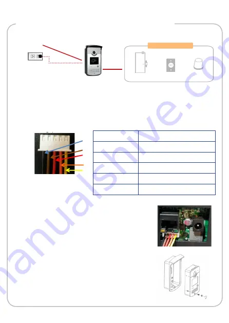
2. Wire and connect input / output devices to the bundled DI/DO cable
connector. Map the cables as below:
Power Source
Network
Door Control
Door Lock
Push Button
Alarm
Wire Color
DI-DO
Black
Normal Open (NO)
Brown
COM
Red
Normal Close (NC)
Orange
DI-
Yellow
DI+
3. Connect the DI/DO cable connector to the
Device.
4. Mount the Device to its housing and attach
the bundled fixing screw to secure the unit.