background image

www.acti.com


Hardware Manual 


26 

Step 4: Connect to Network 

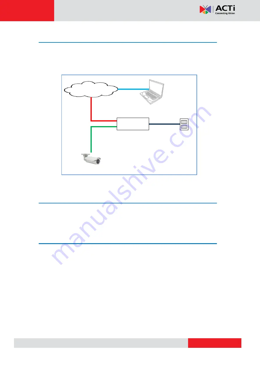
Connect the other end of the network cable to a switch or injector. Then, connect the switch or 

injector to a network, PC, and a power source. See Power-over-Ethernet (PoE) connection 

example below. 


Network 

AC Power 

Source 

PoE Injector 

Power Cable 

Ethernet Cable 

Ethernet Cable 
(Data + Power) 

Ethernet Cable 

(Data) 

Camera 


Step 5: Access the Camera Live View 

See 

Accessing the Camera

 on page 42 for more information on how to access the Live View 

of the camera. 


Step 6: Complete the Installation 

To complete the installation, attach the sunshield to the camera, see 

How to Attach the 

Sunshield

 on page 33. Below is a sample installation. 


Содержание E413

Страница 1: ...Bullet Camera Hardware Manual E48 E413 E415 E416 E417 E418 Ver 2016 02 16...

Страница 2: ...ount the Camera 15 Step 3 Waterproof and Connect the Cable s 17 How to Use the Cable Gland 18 How to Use the Conduit Gland 22 Step 4 Connect to Network 26 Step 5 Access the Camera Live View 26 Step 6...

Страница 3: ...18 36 How to Insert the Memory Card 39 How to Remove the Memory Card 39 How to Reset the Camera 40 Resetting E413 E415 E416 E417 E418 40 Resetting E48 41 Accessing the Camera 42 Configure the IP Addre...

Страница 4: ...attempt to service this video device yourself as opening or removing covers may expose you to dangerous voltage or other hazards Refer all servicing to qualified service personnel Trademarks All names...

Страница 5: ...urning the equipment off and on the user is encouraged to try to correct the interference by one or more of the following measures Reorient or relocate the receiving antenna Increase the separation be...

Страница 6: ...ct this video product from the power supply immediately and refer servicing to qualified service personnel under the following conditions 1 When the power supply or plug is damaged 2 If liquid has bee...

Страница 7: ...LLS Vari focal lens E415 1MP Bullet with D N Adaptive IR Superior WDR Vari focal lens E416 10MP Zoom Bullet with D N Adaptive IR Basic WDR 4 3x Zoom lens E417 2MP Video Analytics Zoom Bullet with D N...

Страница 8: ...nts Camera E413 E415 E417 E418 Camera E48 E416 Bracket Plate Sunshield Mounting Screw Kit Sunshield Screw Kit Conduit Gland Cable Gland Gland Rubber Rings x2 Drill Template Terminal Block Quick Instal...

Страница 9: ...4 Audio Input This jack connects to an audio input device such as a microphone with built in amplifier NOTE Make sure that the connected audio input device has a built in amplifier Connecting an ordi...

Страница 10: ...or more information 4 Digital Input Output Connects to digital input or output devices such as an alarm trigger panic button etc Digital Input DI and Digital Output DO devices are used in applications...

Страница 11: ...naudible recording NOTE 2 If the audio connectors will not be used leave the rubber caps on to ensure cables remain waterproof and eliminate short circuit hazards 8 Audio Output Connects to audio outp...

Страница 12: ...40 for more information 4 Digital Input Output Connects to digital input or output devices such as an alarm trigger panic button etc Digital Input DI and Digital Output DO devices are used in applica...

Страница 13: ...onnects to audio output devices such as a speaker etc NOTE If the audio connectors will not be used leave the rubber caps on to ensure cables remain waterproof and eliminate short circuit hazards 7 Et...

Страница 14: ...If necessary install a memory card into the memory card slot of the camera See How to Insert the Memory Card on page 39 for more information 2 Attach the bracket to the camera 3 Attach the supplied dr...

Страница 15: ...the Cable s on page 17 d Push the cable s into the cable hole of the surface then proceed to Step 2 Mount the Camera below If the camera cable will be routed along the surface continue with the next...

Страница 16: ...the bracket plate to fix its position 3 Attach the camera to the surface using the three 3 supplied screws 4 Adjust the camera installation angle and orientation and then tighten the screws to fix th...

Страница 17: ...when connecting an Exterior grade Ethernet cable between the camera and a Power over Ethernet PoE switch or injector See How to Use the Cable Gland on page 18 Conduit Gland Use this solution when con...

Страница 18: ...ed installation procedures for details Before connection prepare the following materials Cable Gland included in the camera package Washer included in the camera package Exterior Grade Ethernet Cable...

Страница 19: ...Insert the clamping nut into the Ethernet cable 3 Insert the sealing insert with claw 4 Attach one 1 supplied rubber ring on the gland body smooth end NOTE Make sure the rubber ring is completely ali...

Страница 20: ...rnet port of the camera IMPORTANT Make sure the rubber ring is completely aligned and flat on the gland body to avoid possible water leakage 6 Connect the Ethernet cable connector to the pigtail conne...

Страница 21: ...www acti com Hardware Manual 21 8 Attach the clamping nut to the cable gland body Make sure the clamping nut is tightly secured and the sealing rubber is squeezed in to avoid water leakage...

Страница 22: ...e is not available Before connection prepare the following materials Conduit Gland included in the camera package Flexible Conduit 1 2 Trade size not included in the package NOTE Not included in the p...

Страница 23: ...ugh the flex conduit Leave enough length of the cable outside the flex conduit 3 Insert the clamping nut through the flex conduit 4 Insert the sealing nut and fix it at the end of the flex conduit 5 A...

Страница 24: ...nd body 6 Attach the gland body to the Ethernet port of the camera MPORTANT Make sure the rubber ring is completely aligned and flat on the gland body to avoid possible water leakage 7 Connect the Eth...

Страница 25: ...www acti com Hardware Manual 25 9 Attach the clamping nut to the conduit gland body Make sure the clamping nut is tightly secured to avoid water leakage...

Страница 26: ...ample below Network AC Power Source PoE Injector Power Cable Ethernet Cable Ethernet Cable Data Power Ethernet Cable Data Camera Step 5 Access the Camera Live View See Accessing the Camera on page 42...

Страница 27: ...er or dust from entering the connectors Connecting a Power Adapter Optional In case of using a non PoE switch or your PoE switch has limited power supply you can purchase a power adapter and directly...

Страница 28: ...4 Tighten the screws of the 12V pin and the GND pins to secure the wire connection 5 Set the prepared power adapter for connection later Below is an example of a power adapter with an attached termin...

Страница 29: ...amera For example you can connect an alarm horn to the camera as such when an event occurs inside the camera e g detected intruder the alarm horn will sound Other common DO device applications are mot...

Страница 30: ...V 30V or the DO device has a voltage of 24V 50mA then the camera can supply internal power to these devices and there is no need to connect the DI DO device to an external power source In this case us...

Страница 31: ...rcuit voltage has to match the external power supply e g 110V AC or 220V AC The illustration below is a graphic example of connecting a relay to a high voltage DO device Relay DO1 Device Camera Illumi...

Страница 32: ...tput jack GREEN jack of the camera If the camera is installed outdoors be sure to wrap the audio connectors with Waterproof tape can be purchased in hardware stores DISCLAIMER ACTi will not be respons...

Страница 33: ...era will be installed outdoors attach the sunshield to protect the lens from all types of weather and lighting conditions 1 Loosely secure the supplied screws and washers to attach the sunshield 2 Sli...

Страница 34: ...Procedures vary depending on camera model Opening the Back Cover of E48 E416 1 Remove the three 3 screws securing the integrated bracket from the camera back cover and then detach the bracket 2 Loosen...

Страница 35: ...s and the guides of the back cover to the camera NOTE Ensure that the rubber is properly aligned to the cover when closing the back cover 2 Tighten the three 3 screws to secure the back cover 3 Attach...

Страница 36: ...three 3 screws securing the integrated bracket 2 Detach the integrated body from the camera back cover 3 Remove the clamping nut and rubber insert to loosen the cable within the gland NOTE Connectors...

Страница 37: ...wly lift the cover NOTE Connectors are connected inside the camera do not abruptly lift the cover Closing the Back Cover of E413 E415 E417 E418 1 Before closing the back cover make sure rubber on the...

Страница 38: ...38 3 Push the rubber insert into the gland and attach the clamping nut NOTE Make sure the clamping nut is tightly attached to ensure that the connection is waterproof 4 Attach the integrated bracket a...

Страница 39: ...Back Cover of E413 E415 E417 E418 on page 36 2 Insert the memory card with the metallic contacts facing down into the slot until it clicks into place Example of E413 Example of E48 3 Close the back c...

Страница 40: ...ask or allow deny filter related issues resulting with the inability to modify these settings In case of connectivity issues or abnormal video quality Resetting E413 E415 E416 E417 E418 Do the followi...

Страница 41: ...ning Resetting E48 Do the following procedures to access the Reset button and restore the camera its default factory settings 1 Open the camera back cover See Opening the Back Cover of E48 E416 on pag...

Страница 42: ...server running then you do not need to configure the IP addresses at all both the camera and the PC would request a unique IP address from DHCP server automatically In such case the camera will immedi...

Страница 43: ...tool that can not only discover the cameras but also list lots of valuable information such as IP and MAC addresses serial numbers firmware versions etc and allows quick configuration of multiple dev...

Страница 44: ...work and it does not detect any DHCP services it will automatically assign itself a default IP 192 168 0 100 Whereas the default port number would be 80 In order to access that camera the IP address o...

Страница 45: ...P Utility With the procedure shown above all the cameras will have unique IP addresses starting from 192 168 0 101 In case there are 20 cameras selected the last one of the cameras would have the IP 1...

Страница 46: ...Explorer browsers free third party software plug ins must be installed to the PC first to be able to get the live video feed from the camera Browser Required Plug In Safari QuickTime http www apple co...

Страница 47: ...ollowing address into Web browser s address bar http 192 168 0 100 Upon successful connection to the camera the user interface called Web Configurator would appear together with the login page The HTT...

Страница 48: ...Copyright 2015 ACTi Corporation All Rights Reserved 7F No 1 Alley 20 Lane 407 Sec 2 Ti Ding Blvd Neihu District Taipei Taiwan 114 R O C TEL 886 2 2656 2588 FAX 886 2 2656 2599 Email sales acti com...

Отзывы: