ACTi E31A Скачать руководство пользователя страница 24

www.acti.com


Hardware Manual 


24 

3.


Secure the clamping nut to the body. 


NOTE:

 Make sure the clamping nut is tight to avoid possible water leak. 


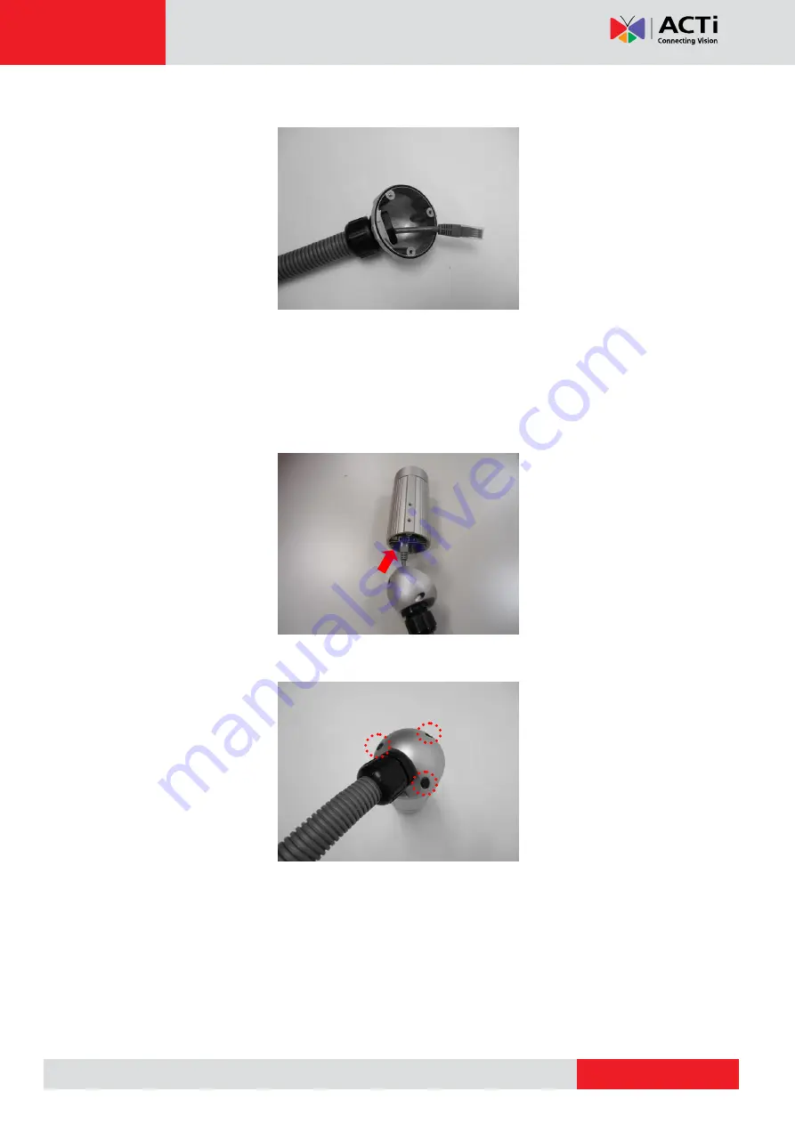
Step 4: Connect the Ethernet Cable 


1.


Connect the Ethernet cable to the Ethernet port inside the camera. 


2.


When done, close the back cover by tightening the three (3) screws. 


NOTE:

 Make sure the rubber ring on the cover is secured and the screws are completely 

tightened to avoid possible water leak. 


Содержание E31A

Страница 1: ...Bullet Camera Series Hardware Manual E31A E32A E33A E35 E36 E37 Ver 2015 11 02 ...

Страница 2: ... Step 5 Connect the Cable 15 Step 6 Access the Camera Live View 15 Cable Management Options 16 Using the Round Shaped Connector with Cable Gland 16 Using the Waterproof Tape 19 Using the Bundled Conduit Gland 20 Other Adjustments and Accessories 25 How to Install Remove the Memory Card 25 How to Insert the Memory Card 25 How to Remove the Memory Card 26 How to Reset the Camera 27 How to Adjust the...

Страница 3: ...www acti com Hardware Manual 3 Using the Default Camera IP Address 33 Access the Camera 35 ...

Страница 4: ...opening or removing covers may expose you to dangerous voltage or other hazards Refer all servicing to qualified service personnel Trademarks ACTi and ACTi logo are registered trademarks of ACTi Corporation All other names and products used in this manual are registered trademarks of their respective companies Liability Every reasonable care has been taken during the writing of this manual Please ...

Страница 5: ...turning the equipment off and on the user is encouraged to try to correct the interference by one or more of the following measures Reorient or relocate the receiving antenna Increase the separation between the equipment and receiver Connect the equipment into an outlet on a circuit different from that to which the receiver is connected Consult the dealer or an experienced radio TV technician for ...

Страница 6: ...ly immediately and refer servicing to qualified service personnel under the following conditions 1 When the power supply cord or plug is damaged 2 If liquid has been spilled or objects have fallen into the product 3 If the inner parts of product have been directly exposed to rain or water 4 If the product does not operate normally even by following the operating instructions in this manual Adjust ...

Страница 7: ...xed lens E32A 3MP Bullet with D N Adaptive IR Basic WDR Fixed lens E33A 2MP Bullet with D N Adaptive IR Basic WDR SLLS Fixed lens E34A 5MP Bullet with D N Adaptive IR Basic WDR Fixed lens E35 3MP Bullet with D N Adaptive IR Superior WDR Fixed lens E36 1 3MP Bullet with D N Adaptive IR Basic WDR SLLS Fixed lens E37 10MP Bullet with D N IR Basic WDR Fixed lens ...

Страница 8: ...www acti com Hardware Manual 8 Package Contents Camera Sunshield Sunshield Screw Kit Bracket Bracket Plate Lens Focus Tuner not available in E37 Conduit Gland Quick Installation Guide Warranty ...

Страница 9: ...factory default settings To do the reset press and hold the Reset button for at least 5 seconds or until the Power LED lights up When the Power LED lights up again reset is complete See How to Reset the Camera on page 27 3 Power LED The Power LED lights up when the camera is connected to the power source and goes off once the camera boot up process is complete NOTE For typical use the power LED is...

Страница 10: ...se with the camera Mount Types Accessories Corner Mount Suitable when mounting the camera on a corner wall PMAX 1107 PMAX 0402 Pole Mount Suitable when mounting the camera on a pole PMAX 1107 PMAX 0503 NOTE For more information about the mounting solutions and accessories please check the Mounting Accessory Selector in our website http www acti com mountingselector The above mounting accessories a...

Страница 11: ... the location of the three 3 screw holes using the bracket plate included in the package NOTE Depending on the surface where you will install the camera it may be necessary to drill the holes and use the supplied screw tox 2 Attach the plate to the surface using the three 3 supplied screws 3 Attach the bracket to the plate ...

Страница 12: ...ra will be installed outdoors attach the sunshield to protect the lens from all types of weather and lighting conditions 1 Loosely secure the supplied screws and washers to attach the sunshield 2 Slide to adjust the sunshield to cover the lens as far as possible but out of the camera s live view 3 Tighten the screws to fix the position of the sunshield ...

Страница 13: ...see Step 4 Waterproof and Connect the Cable on page 14 Some methods may require the cable to be waterproof first before installing the camera to its bracket 1 Depending on how you want to install the camera attach the camera to the bracket through one of the two 2 holes below 2 Adjust the camera viewing angle and tighten the knob to fix the camera position ...

Страница 14: ...abling options applicable to the connector that came with the camera Cabling Options Round Shaped Connector Square Shaped Connector Using the Round Shaped Connector with Cable Gland Applicable when using an exterior grade Ethernet cable to connect to the camera Bundled cable gland provides complete waterproof solution See Using the Round Shaped Connector with Cable Gland on page 16 Yes No Using th...

Страница 15: ... injector to a network PC and a power source See Power over Ethernet PoE connection example below Network AC Power Source PoE Injector Power Cable Ethernet Cable Ethernet Cable Data Power Ethernet Cable Data Camera Step 6 Access the Camera Live View See Accessing the Camera on page 31 for more information on how to access the Live View of the camera ...

Страница 16: ... it inside a junction box or doing any of the following cabling options to protect the cable connection Using the Round Shaped Connector with Cable Gland This section describes how to waterproof the round shaped cable connector of the camera using the bundled cable gland Before connection prepare the following materials An exterior grade Ethernet cable without the RJ 45 connector RJ 45 connector C...

Страница 17: ...ert the clamping nut into the Ethernet cable without connector 4 Insert the cable through the gland body 5 Attach the RJ 45 connector to the cable For pin mapping and detailed instructions see How to Attach the RJ 45 Connector on page 29 for detailed information Gland Body Clamping Nut ...

Страница 18: ...o the camera connector 7 Attach the gland body to the camera connector 8 Attach the clamping nut to the gland body to complete the cable solution NOTE Make sure the clamping nut is tightly attached to the cable gland body and the sealing insert is squeezed tightly ...

Страница 19: ...hernet port of the camera and wrap the connection with waterproof tape to complete the installation NOTES on using Ethernet cables For outdoor installations it is recommended to use exterior grade Ethernet cables CAT5 CAT5e CAT6 ordinary Ethernet cables are only designed for indoor use and may deteriorate quickly when exposed to outdoor elements Exterior grade Ethernet cables are waterproof and do...

Страница 20: ...s recommended to use a flexible conduit with 1 2 diameter and the conduit gland included in the package to protect the camera cabling In this case the pre installed network cable with pigtail female connector must be replaced with a standard Ethernet cable NOTE The flexible conduit and Ethernet cable are not included in the package and must be sold separately When purchasing make sure the flex con...

Страница 21: ...e Pigtail 1 Loosen the three 3 screws to detach the back cover NOTE A cable is connected inside the camera do not abruptly pull the back cover 2 Disconnect the network connector 3 Remove the pre installed cable gland and network cable using a wrench not included in the package ...

Страница 22: ...Prepare the Conduit Gland and Flex Conduit 1 Disassemble the bundled conduit gland as shown below 2 Pull the Ethernet cable through the flex conduit 3 Insert the clamping nut through the flex conduit Clamping Nut Sealing Insert Lock Nut Body ...

Страница 23: ...t and attach it at the end of the flex conduit Step 3 Install the Ethernet Cable 1 Insert the body A to the back cover and secure it with the lock nut B 2 Insert the Ethernet cable through the back cover and then align the sealing insert to the gland body A B ...

Страница 24: ...void possible water leak Step 4 Connect the Ethernet Cable 1 Connect the Ethernet cable to the Ethernet port inside the camera 2 When done close the back cover by tightening the three 3 screws NOTE Make sure the rubber ring on the cover is secured and the screws are completely tightened to avoid possible water leak ...

Страница 25: ... supports local video recording or saving of snapshots to a memory card NOTE Supports microSDHC and microSDXC cards How to Insert the Memory Card 1 Loosen the three 3 screws to detach the back cover NOTE A cable is connected inside the camera do not abruptly pull the back cover 2 Insert the memory card into the card slot with the metallic contacts facing down and push the card until it clicks into...

Страница 26: ...the rubber seal is properly attached and the back cover is closed to ensure water or dust cannot enter the camera How to Remove the Memory Card In case there is a need to remove the card make sure to access the camera Web Configurator to safely unmount the card first see the camera Firmware manual for more information Once unmounted from the firmware push the card to eject it from the slot ...

Страница 27: ... the camera do not abruptly pull the back cover 2 Using a pointed object such as the tip of a pen press and hold the Reset button for at least 5 seconds or until the Power LED lights up to reset the camera 3 When done ensure the rubber seal is aligned and attached to the back cover and then close the back cover by tightening the three 3 screws CAUTION Make sure the rubber seal is properly attached...

Страница 28: ...front cover 2 Attach the lens focus tuner to the lens 3 Adjust the focus of the target area based on the live view of the camera see Access the Camera on page 35 4 When done close the front cover CAUTION The front cover must be tightly closed to ensure water or dust does not go through any opening ...

Страница 29: ... Cut about one 1 inch into the plastic sheath from the end of the cable 3 Unwind the wires and arrange them according to the color sequence below This side up 1 Stripe Orange 2 Orange 3 Stripe Green 4 Blue 5 Stripe Blue 6 Green 7 Stripe Brown 8 Brown 4 Straighten out the wires and use the scissors to make a straight cut inch from the cut end ...

Страница 30: ...anual 30 5 With the RJ 45 connector tab facing down push down the wires into the connector all the way to the end 6 Place the connector into the crimping tool and cinch down to secure the RJ 45 connector to the Ethernet cable ...

Страница 31: ...HCP server running then you do not need to configure the IP addresses at all both the camera and the PC would request a unique IP address from DHCP server automatically In such case the camera will immediately be ready for the access from the PC The user however might not know the IP address of the camera yet It is necessary to know the IP address of the camera in other to be able to access it by ...

Страница 32: ...e tool that can not only discover the cameras but also list lots of valuable information such as IP and MAC addresses serial numbers firmware versions etc and allows quick configuration of multiple devices at the same time Search and downloand IP Utility for free from http www acti com DownloadCenter With just one click you can launch the IP Utility and there will be an instant report as follows Y...

Страница 33: ...twork and it does not detect any DHCP services it will automatically assign itself a default IP 192 168 0 100 Whereas the default port number would be 80 In order to access that camera the IP address of the PC has to be configured to match the network segment of the camera Manually adjust the IP address of the PC In the following example based on Windows 7 we will configure the IP address to 192 1...

Страница 34: ... IP Utility With the procedure shown above all the cameras will have unique IP addresses starting from 192 168 0 101 In case there are 20 cameras selected the last one of the cameras would have the IP 192 168 0 120 Later by pressing the Refresh button of the IP Utility you will be able to see the list of cameras with their new IP addresses Please note that it is also possible to change the IP addr...

Страница 35: ... Explorer browsers free third party software plug ins must be installed to the PC first to be able to get the live video feed from the camera Browser Required Plug In Safari QuickTime http www apple com quicktime download Other non Internet Explorer browsers Basic VLC Media Player http www videolan org Disclaimer Notice The camera manufacturer does not guarantee the compatibility of its cameras wi...

Страница 36: ...er s address bar http 192 168 0 100 Upon successful connection to the camera the user interface called Web Configurator would appear together with the login page The HTTP port number was not added behind the IP address since the default HTTP port of the camera is 80 which can be omitted from the address for convenience Before logging in you need to know the factory default Account and Password of ...

Страница 37: ...Copyright 2015 ACTi Corporation All Rights Reserved 7F No 1 Alley 20 Lane 407 Sec 2 Ti Ding Blvd Neihu District Taipei Taiwan 114 R O C TEL 886 2 2656 2588 FAX 886 2 2656 2599 Email sales acti com ...

Отзывы: