For ATRx ProxTime and ATRx10 setup, begin with
Step 1; for ATRx20 setup, begin with Step 5.
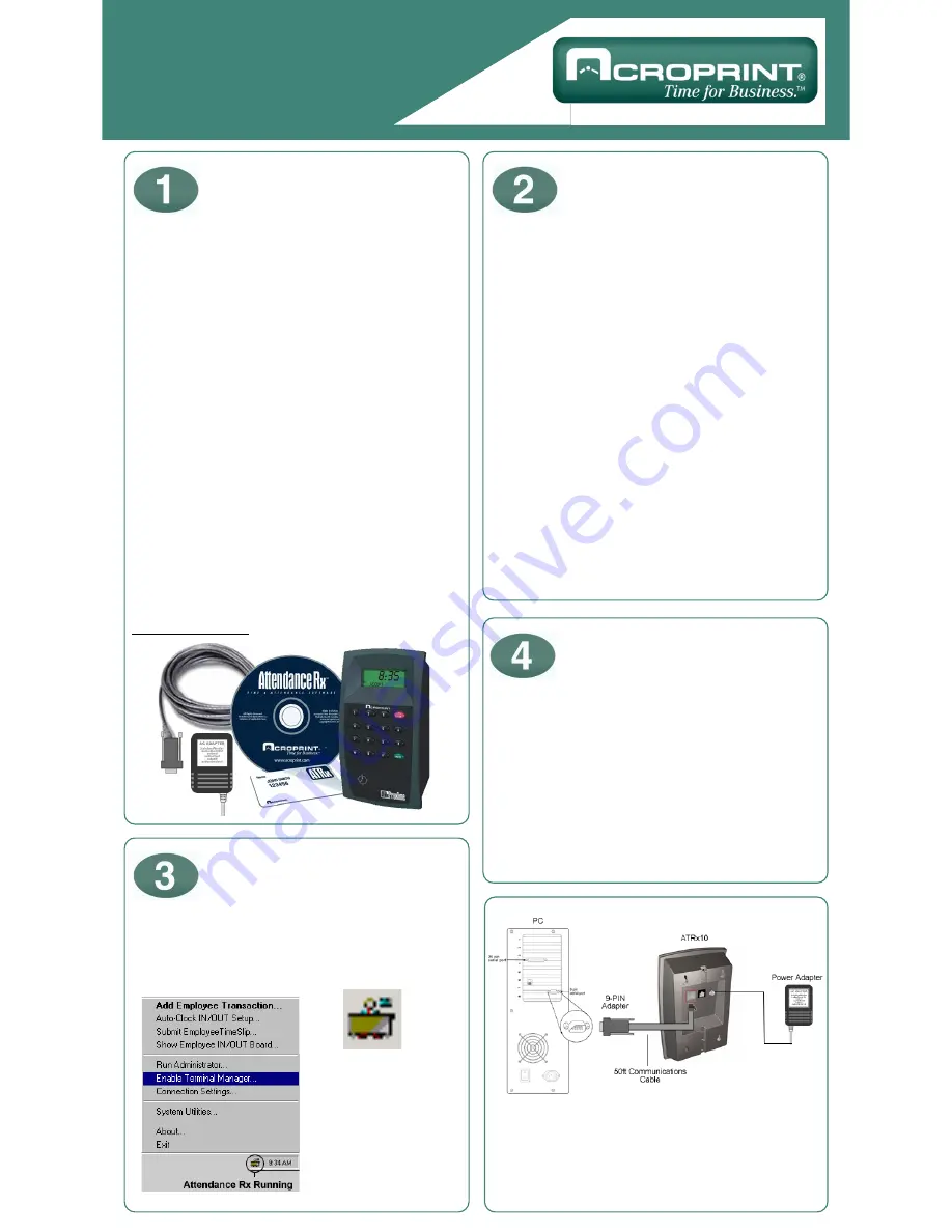
ATRx ProxTime System includes:
• Attendance Rx™ software
(may already be installed, PN: 08-0137-000)
• ATRx ProxTime™
(
ATRx 10 Proximity Terminal, PN: 01-0206-000)
• 50 ft. RS232 ATR Communications Cable
provided by Acroprint
(PN: 72-0195-000)
• RJ11/DB 9-pin ATR Serial Adapter
provided by Acroprint
(PN: 63-0163-003)
• 12V DC Power Adapter
(PN: 56-0126-000)
• 15 Proximity Badges
(PN: 14-0123-002)
Install Attendance Rx software by inserting CD into
CD-Rom (unless already installed). Follow and
complete the installation wizard.
To ensure the PC meets the minimum system
requirements, see product box or refer to
www.acroprint.com.
ATRx ProxTime Quick Start
www.acroprint.com
1.
To avoid damage to the PC port; PC power must be
completely shutdown prior to attaching the ATR adapter
and ATR communications cable.
2. Connect ATR adapter and ATR communications
cable (this may already be connected at the factory).
3. Connect the ATR adapter to the serial port on the
back of PC.
4. Connect the ATR communications cable to the
white RS232 port on the back of the ATRx10
proximity terminal.
** Do not connect to a telephone wall outlet.
** Do not connect to a modem port.
5. Plug the 12V DC Power Adapter into the back of
the ATRx10 proximity terminal and the wall outlet.
The terminal will display the letters
-PC-
on the LCD
screen.
Turn PC on and Attendance Rx software should start.
To confirm software is running
, a System Tray Icon
will appear in the bottom right-hand corner of
your computer desktop screen.
To enable ATRx
Terminal Manager, right
click the System Tray
icon, select
Enable
Terminal Manager
.
After enabling the Terminal Manager the software will
automatically locate the PC serial port. The Time
and Day of the week will display on the ATRx10
screen.
Note: If the Time and Day of week do not display,
-PC-
will remain on the ATRx10 screen. If this
occurs, repeat Quick Start Step 2 to ensure connec-
tions are correct and proceed to Trouble Shooting
portion on the reverse side of the Quick Start Sheet.
Getting Started
Connect ATRx10
to Windows Based PC
Power Connection
Verify Terminal is
Communicating with PC
After following these steps, your set-up
should look like this diagram.
*Use enclosed wall template and four screws
to mount unit to wall stud.
Part Number: 06-0319-000


