


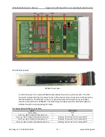


VPX4812A/4814A
User’s Manual
Single-Slot 3U VPX Bus XMC Carrier Card/Switch Card Module
Acromag, Inc. Tel: 248-295-0310 - 15 - www.acromag.com
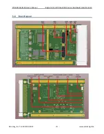
7.0
Switch Settings
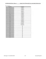
The following describes the VPX4812A switches with their default positions and their functions.
SW1
–
Upstream Port Selection
Switch Position
Selected Upstream Port
1
2
3
4
ON
ON
ON
ON
VPX Fat Pipe A (default)
OFF
ON
ON
ON
VPX Fat Pipe B
OFF
ON
OFF
ON
VPX Fat Pipe C
ON
OFF
OFF
ON
VPX Fat Pipe D
ON
ON
ON
OFF
XMC
SW2
(FRUSEL)
1-2 (default)
FRU uses 3.3V
2-3
FRU uses 3.3V_AUX
4-5
Unused
5-6
Unused
SW3-1
(STATION 0 PORT
CONFIG)
ON (default)
VPX Fat Pipe A = x4, VPX Fat Pipe B = x4
OFF
VPX Fat Pipe A = x8, VPX Fat Pipe B = Disabled
SW3-2
(STATION 1 PORT
CONFIG)
ON
VPX Fat Pipe C = x8, VPX Fat Pipe D = Disabled
OFF (default)
VPX Fat Pipe C = x4, VPX Fat Pipe D = x4
SW3-3
(PCIE LINK
SPEED)
ON
Force Gen 1.0 Speed Only
OFF (default)
Allow Gen 1.0 & Gen 2.0 Speeds
SW3-4
(XMC VPWR
VOLT SELECT)
ON
VPWR = +12V
OFF (default)
VPWR = +5V