


SERIES IOS-320 I/O SERVER MODULE 12-BIT HIGH DENSITY ANALOG INPUT BOARD
__________________________________________________________________________________________
- 3 -
Acromag, Inc. Tel:248-295-0310 Fax:248-624-9234 Email:[email protected] http://www.acromag.com
I/O SERVER MODULE INTERFACE FEATURES
High density -
Single-size, industry standard, IOS module
footprint. Four units mounted on a carrier board provide up
to 80 differential or 160 single-ended channels.
Local ID
- Each IOS module has its own 8-bit ID PROM
which is accessed via data transfers in the "ID Read" space.
16-bit I/O
- Control register Read/Write and A/D
Conversion/Read are performed through 16-bit data transfer
cycles.
I/O SERVER MODULE SOFTWARE
IOS MODULE Win32 DRIVER SOFTWARE
Acromag provides a software product (sold separately) to
facilitate the development of Windows Embedded Standard
applications interfacing with I/O Server Modules installed on
Acromag Industrial I/O Server systems. This software (Model
IOSSW-DEV-WIN) consists of a low-level driver and Windows
32 Dynamic Link Libraries (DLLS) that are compatible with a
number of programming environments including Visual C++,
Visual Basic.NET, Borland C++ Builder and others. The DLL
functions provide a high-level interface to the IOS carrier and
modules eliminating the need to perform low-level reads/writes
of registers, and the writing of interrupt handlers.
IOS MODULE LINUX SOFTWARE
Acromag provides a software product (sold separately)
consisting of Linux software. This software (Model IOSSW-
API-LNX) is composed of Linux libraries designed to support
applications accessing I/O Server Modules installed on
Acromag Industrial I/O Server systems. The software is
implemented as a library of “C” functions which link with
existing user code.
2.0 PREPARATION FOR USE
UNPACKING AND INSPECTION
Upon receipt of this product, inspect the shipping carton for
evidence of mishandling during transit. If the shipping carton is
badly damaged or water stained, request that the carrier's agent
be present when the carton is opened. If the carrier's agent is
absent when the carton is opened and the contents of the carton
are damaged, keep the carton and packing material for the
agent's inspection.
For repairs to a product damaged in shipment, refer to the
Acromag Service Policy to obtain return instructions. It is
suggested that salvageable shipping cartons and packing
material be saved for future use in the event the product must be
shipped.
This board is physically protected with
packing material and electrically
protected with an anti static bag during
shipment. It is recommended that the
board be visually inspected for
evidence of mishandling prior to
applying power.
The board utilizes static sensitive
components and should only be
handled at a static-safe workstation.
BOARD CONFIGURATION
The board may be configured differently, depending on the
application. All allowable jumper settings are discussed in the
following sections. Jumper locations are shown in the drawing in
the end of this manaul.
Power should be removed from the board when configuring
hardware jumpers, installing IOS modulesIP's, cables,
termination panels and field wiring. Refer to the Analog Input
Connection Diagram on page 15 and IOS documentation for IOS
configuration and assembly instructions.
Default Hardware Jumper Configuration
A board shipped from the factory is configured as follows:
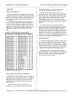
Analog input range is configured for a 10V bipolar input span
(i.e. an ADC input range of -5 to +5 Volts).
Internal 12 Volt power supplies are used (sourced from P1
connector).
Programmable software control register bits are set at logic
low during power-up reset. The control register should be
programmed to the desired gain, mode, and channel
configuration before starting ADC analog input acquisition.