SERIES AP220 / AP231 ACROPACK
USER
’S MANUAL
Acromag, Inc. Tel: 248-295-0310
- 20 -
http://www.acromag.com
- 20 -
https://www.acromag.com
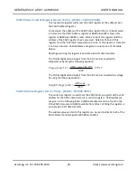
5
0
Fixed at 0
6
Thermal shutdown alert
0
Die temperature > 150C do not power down
1
Die temperature > 150C power down
7
Data Format Control Bit
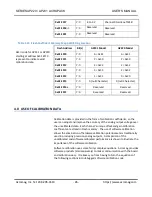
When a channel is configured for 0-10 or 0-5 ranges, this bit is
ignored and anything written to the DAC is treated as straight
binary. See Table 3.6 for example corresponding codes.
0
Straight binary coded or Bipolar Offset Binary coded
1
Twos complement coded
8
5% Over-range
0
5% over-range disable
1
5% over-range enable
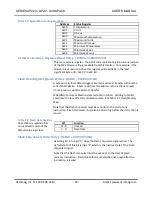
10 to 9
2-bits Clear voltage selection
00
Zero scale
01
Midscale
10
Full scale
11
Full scale
11
Brownout condition status on readback
0
No brownout condition
1
Brownout condition detected
12
Short-circuit condition status on readback
0
No short circuit condition
1
Short-circuit condition detected
15 to 13
Not Used
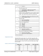
Output Data Format
The default bipolar output range (-10 to +10 Volts) is programmed with
straight binary with default setting. However, twos complement can also be
select via the write to DAC control register. The following table indicates the
relationship between the data format and the ideal analog output voltage
from the module.
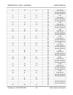
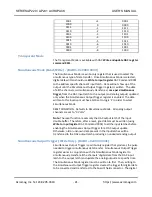
Table 3.6 DAC Channel Data Format
Straight Binary
Decimal Code
Twos Complement
1111
+7
0111
1110
+6
0110
1101
+5
0101
1100
+4
0100
1011
+3
0011
1010
+2
0010

