3×40W
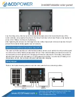
Use the string wires, directly secure the input and output wires into the terminal holes of the
solar controller, screw tightly the wires to the “Solar” terminal to the Solar Panel. screw tightly the
wires to the “Battery” terminal to the Battery.
After tightening the screws, do not forget to fix the rubber mask back to the terminal box, this will
protect the metal terminals against rust or moisture.
The solar controller provides an external temperature sensor,as an option,the unit provides aport
to connect the external battery temperature sensor; if the external battery temperature sensor is
connected,the unit will optimize the charging performance subjected to the battery temperature
detected and also provide the battery over temperature protection, in some case,if battery over
temperature occurs, the controller will auto matically stop charging.
Optional external Battery Temperature Sensor BTS
Refer to the below drawing, please cover the solar panel before connecting cables.
Wiring diagram
Содержание PWM20A
Страница 1: ...560mm 22in 440mm 17 3in 4 5 Product Introduction 3 40W 1 3 9 8 2 6 7 10 560mm 22in 1440mm 56 7in...
Страница 18: ...3 40W...
Страница 19: ...3 40W...


