2. MOUNTING
Flush-mounted version
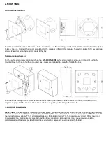
The standard installation box Φ60 mm is flush mounted so that the mounting holes
1
are level. We insert cables through the
holes in the box. Connect the reader according to the diagram further in this manual. The set includes TX10 key and two
screws
2
used for fixing the reader module to the box.
Surface-mounted version
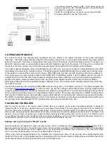
For the surface-mounted version, purchase the
INS-P-XXS-60 NT
surface-mounted box and use it instead of the flush-
mounted box. In the set of surface mounted box screws are included to screw the front to the box.
Lead the wires through hole
1
. Holes
2
are used for screwing the box with studs. Connect the reader according to the
diagram on page 3 of this manual. Close the reader housing using a TX10 key with screws
3
.
3. WIRING DIAGRAM
Please note!
To ensure proper functioning and use safety, connect the door entry unit to earth by connecting the grounding
terminal on unit’s body with relevant protective installation (PE). Use a 1mm
2
cross-section cable (such as LY1,0) to connect
the device to power supply. The maximum cable length for E-lock circuit is 7 m, for power supply circuit - 30 m. Insufficient
power supply, too small cable cross-section and too long connections (voltage drops) may cause device operation
disturbances (such as reset system trip and device restarting, especially when opening the E-lock).


