Acnodes RMMWQ8190 Скачать руководство пользователя страница 4

P.1

Option 

: DC power

< 1.1 > Package Content  

< Part 1 >  

RMWQ8190 

unit  X 1 

- 6ft VGA cable  X 1
- Power adapter  X 1
- Power cord  X 1

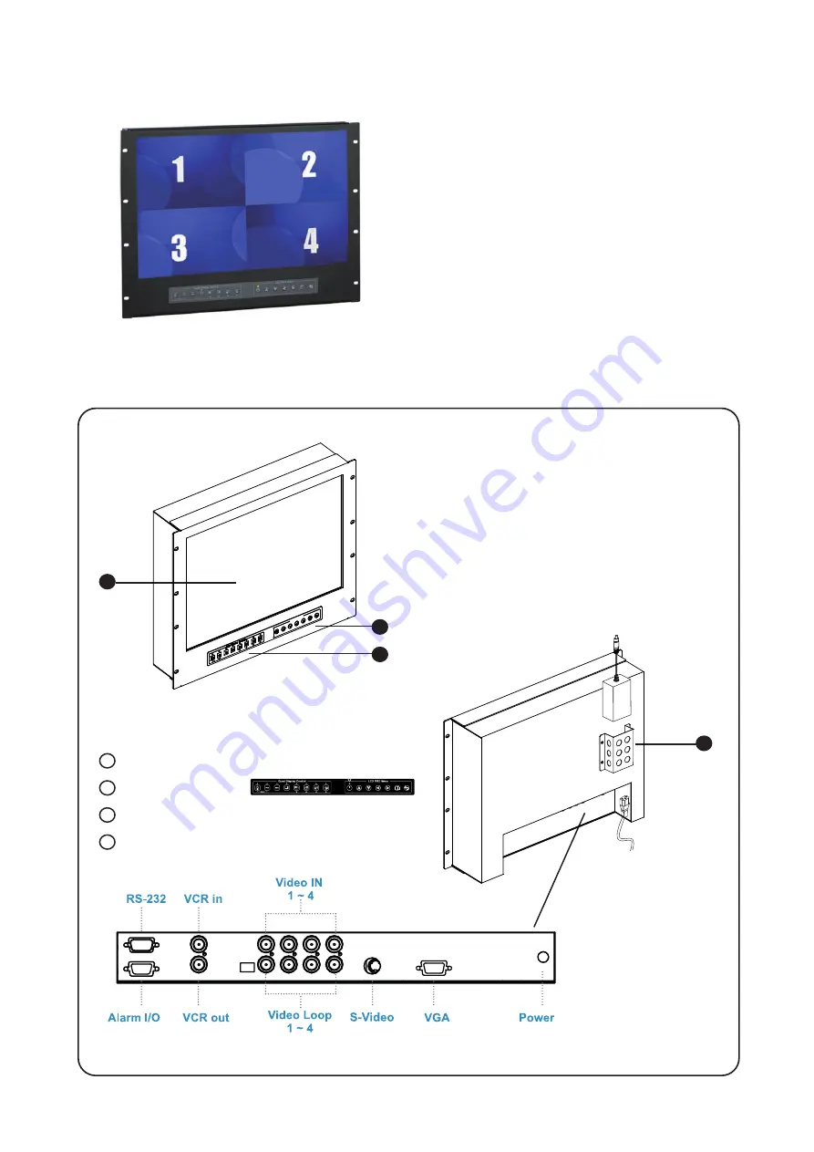
< 1.2 > Structure Diagram  

1

Front view

Rear view

4

Power adapter

Power cord

3

LCD panel

LCD OSD membrane

Quad display control membrane

Power adapter basket

1

2

2

4

3

Содержание RMMWQ8190

Страница 1: ...ll rights reserved Product description and product specifications are subject to change without notice For latest product information please visit Acnodes website at www acnodes com 14628 Central Ave Chino CA91710 Tel 909 597 7588 Fax 909 597 1939 Copyright 2019 Acnodes Corp ...

Страница 2: ...pen the chassis Opening it yourself could damage the equipment and invalidate its warranty If any part of the equipment becomes damaged or stops functioning have it checked by qualified service personnel What the warranty does not cover Any product on which the serial number has been defaced modified or removed Damage deterioration or malfunction resulting from Accident misuse neglect fire water l...

Страница 3: ...RMWQ8190 1 1 Package Content 1 2 Structure Diagram Dimension 1 3 Installation Contents P 1 P 1 2 P 3 Contents Quad Display Connection Operation 4 1 QD Connection 4 2 QD ALARM Connection Operation 4 3 QD Remote Control Connection Operation 4 4 QD OSD Operation 4 5 QD On screen Menu 4 6 QD VCR Operation 4 7 QD Specification P 8 P 9 10 P 11 15 P 16 P 17 19 P 20 P 20 ...

Страница 4: ...t Part 1 RMWQ8190 unit X 1 6ft VGA cable X 1 Power adapter X 1 Power cord X 1 1 2 Structure Diagram 1 Front view Rear view 4 Power adapter Power cord 3 LCD panel LCD OSD membrane Quad display control membrane Power adapter basket 1 2 2 4 3 ...

Страница 5: ...T mm 1mm 0 03937 inch Bottom View Model Product Dimension W x D x H Packing Dimension W x D x H Net Weight Gross Weight RMWQ8190 480 x 72 5 x 354 8 mm 18 9 x 2 9 x 14 inch 539 x 129 x 529 mm 21 2 x 5 1 x 20 8 inch 9 5 kg 20 9 lb 12 5 kg 27 5 lb ...

Страница 6: ... LC D OS D Me nu Setu p VCR SEQ Qu ad Dis pla y Co ntr ol LC D OS D Me nu 1 3 Installation Step Mount the display panel with M6 screw set M6 screw x 8 pcs required Left right side M6 screw sets are not provided 1 Step Fix the LCD into the rack 2 ...

Страница 7: ...ature 20 to 60 C degree Humidity 5 90 non condensing Altitude 40 000 ft Shock 10G acceleration 11ms duration Vibration 5 500Hz 1G RMS random Video Connectivity Analog VGA Analog 0 7Vp p LCD Panel Manufacturer Panel Size diagonal 19 inch Widescreen TFT color LCD Display pixel dots x lines 1440 x 900 Brightness typ 250 Contrast Ratio typ 1000 1 Color 16 7 M Viewing Angle L R U D 85 85 80 80 Response...

Страница 8: ... 5 kg 27 5 lb All dimensions stated are subject to change if options are selected integrated to base model part codes Applicable Format VGA Input PC Signal 1440 x 900 x 60Hz 1280 x 1024 x 60 75Hz 1280 x 960 x 60Hz 1280 x 768 x 60 75Hz 1152 x 864 x 75Hz 1024 x 768 x 60 70 75Hz 848 x 480 x 60Hz 800 x 600 x 60 72 75Hz 720 x 400 x 70Hz 640 x 480 x 60 72 75Hz 640 x 400 x 70Hz 640 x 350 x 70Hz ...

Страница 9: ...y the OSD menu Power on off LCD Power light Green On Orange Power saving Membrane Switch Function OSD Configuration Page Image for the brightness contrast color temp red green and blue Geometry for the auto adjust H position V position phase and clock Video for the colour tint sharpness noise reduction DCDi and TV Setup Audio for volume bass treble balance AVL and mute Misc for the language OSD po...

Страница 10: ...75V 66 160V Input current No load 50 mA 50 mA 50 mA 35 mA Full load 4950 mA 2450 mA 1220 mA 749 mA Output rating Output voltage 12 Volt 12 Volt 12 Volt 12 Volt Output current 4 16A 4 16A 4 16A 6 25A Efficiency 84 85 85 91 3 1 Options DC Power Part 3 1 If the unit with LCD earthing may be required For DC power option ...

Страница 11: ...i Z impedance Incorrect termination will degrade the quality of the video signal All video inputs not looped through to another device the corresponding switches need to be set to 75Ω termination position If another device is connected to video out loop through connector set the corresponding termination switch to Hi Z position Any device connected to the video out loop through connectors needs to...

Страница 12: ... an ordinary VCR to record for longer period of time Combined with alarm sensor detection the VCR will record only when an alarm sensor is activated If more than one sensor have been trigged VCR will start to record after the last trigged event In order to make use of the alarm called full screen display function the VIDEO IN connector from the VCR has to be connected to LIVE monitor connector of ...

Страница 13: ...the Alarm Reset In contact pin 5 of the female type 9 pin D sub connector 8 to GND 2 The Alarm Duration time elapses 3 If the device is operated under Security Lock ON mode Push Lock button for 2 seconds to disable the function then push any button in the front panel 4 Video Loss Alarm Loss of video at any input is automatically detected by the device The device will Activate the built in buzzer S...

Страница 14: ...P 11 h i z 1 2 3 4 75 IN OUT RS 232 ALARM dc 12V 1amp monitor vcr I O RS 232 Cable Wire Computer Remote Keypad Rear Panel 4 3 QD Remote Control Connection Operation ...

Страница 15: ...er can be connected to the male type 9 pin D sub connector on the real panel from it RS 232 port to control this device using standard uppercase ASCII codes 2 1 The ASCII command codes for the quad are listed in the table below The transmission protocol is 1200 baud rate 8 data bit 1 start bit 1 stop bit and no parity Pin Assignment for Remote Control Connector 1 GND 4 NC 7 VCC 2 RX 5 NC 8 GND 3 T...

Страница 16: ...tup menu is switched ON by sending VCR DVR and Lock button codes together 4 Text Select and Cursor Control functions can be performed only under menu Setup mode 2 2 Right after computer terminal has sent out the above mentioned control command code to the device the device will respond with following status code back to computer through RS 232 port Status Code Quad Status Status Code Quad Status E...

Страница 17: ...t status of the alarm operations of the unit BYTE 1 Status code for normal operation modes Channel Select 1110 CH1 1101 CH2 1011 CH3 0111 CH4 Display Mode 0 Quad screen display 1 Full Screen display Auto sequencing mode 0 Auto sequencing mode 1 Quad or full screen mode VCR mode 0 VCR operation 1 Live operation Security Lock mode 0 Security lock ON mode 1 Security lock OFF mode Menu Setup mode 00 M...

Страница 18: ...E 2 Status code for alarm operations The first 4 bits show the sensor activated alarm status of each channel next 4 bits show the video loss alarm status of each channel The digit 1 means alarm event is detected and 0 means no alarm event is detected b7 b6 b5 b4 b3 b2 b1 b0 CH4 CH3 CH2 CH1 CH4 CH3 CH2 CH1 b7 b4 Sensor Activated Alarm b3 b0 Video Loss Alarm 4 3 QD Remote Control Connection Operatio...

Страница 19: ...tons Push these two buttons simultaneously to get into Menu Setup mode and display page 1 of system setup menu Push these two buttons simultaneously again to display page 2 of the setup menu Use page 1 to program time date and camera title and page 2 to configure alarm operations Under menu setup mode Channel Select buttons 5 are used for cursor control and text selection to program the setup menu...

Страница 20: ... be entered for each video channel The available alphanumeric characters are 0 1 2 3 4 5 6 7 8 9 A B C D X Y Z space 1 2 DWELL Time setup The Dwell time menu permits setting the dwell time for all cameras and the Quad Screen on the LIVE output channel The menu shows a table of all cameras and associated dwell time Dwell time can be programmed by setting a number between 00 to 99 for each channel i...

Страница 21: ...nected type of sensor a blinking message will display In this case the buzzer will be activated when you exit the setup operation 2 2 Alarm Sensitivity Alarm sensitivity can be programmed to different extent by setting the period of the trigged pulse detected by the sensor The available settings are 100ms 200ms 300ms 400ms 500ms 600ms 700ms and 800ms 2 3 Alarm Hold Duration The alarm hold duration...

Страница 22: ... mode is desired first turn the quad display button 4 to ON to set the unit to display in the quad mode At this time you may press any of the four channel selection buttons 5 to freeze the corresponding channel 7 2 Under Zoom On VCR playback mode if the unit is showing quad screen pushing the channel selection but tons 5 will call up the specific channel to display in full screen Push the same cha...

Страница 23: ...PAL Number of Color 16 7 M 16 7 M Imaging System NTSC PAL Resolution 1024 x 525 1024 x 625 Refresh Rate 60 50 Video Input Camera Input 1 0 Vpp 75 Ohm x 4 VCR Input 1 0 Vpp 75 Ohm x 1 Video Output Live Monitor 1 0 Vpp 75 Ohm x 1 Loop Through Out 1 0 Vpp 75 Ohm x 4 VCR Output 1 0 Vpp 75 Ohm x 1 Auto Gain Control Yes Time Date Yes On Screen Display Yes Camera Title 8 Character Title Display Format 2 ...

Отзывы: