background image

Legal Information


First English printing, October 2002


Information in this document has been carefully checked for accuracy; however, no guarantee is given to the correctness of the 
contents. The information in this document is subject to change without notice. We are not liable for any injury or loss that results from 
the use of this equipment.


Safety Instructions


Please read all of these instructions carefully before you use the device. Save this manual for future reference.


■ Unplug equipment before cleaning. Don’t use liquid or spray detergent; use a moist cloth.
■ Keep equipment away from excessive humidity and heat. Preferably, keep it in an air-conditioned environment with

temperatures not exceeding 40º Celsius (104º Fahrenheit).

■ When installing, place the equipment on a sturdy, level surface to prevent it from accidentally falling and causing

damage to other equipment or injury to persons nearby.

■ When the equipment is in an open position, do not cover, block or in any way obstruct the gap between it and the

power supply. Proper air convection is necessary to keep it from overheating.

■ Arrange the equipment’s power cord in such a way that others won’t trip or fall over it.
■ If you are using a power cord that didn’t ship with the equipment, ensure that it is rated for the voltage and current

labeled on the equipment

’s electrical ratings label. The voltage rating on the cord should be higher than the one listed

on the equipment

’s ratings label.


■ Observe all precautions and warnings attached to the equipment.
■ If you don’t intend on using the equipment for a long time, disconnect it from the power outlet to prevent being

damaged by transient over-voltage.

■ Keep all liquids away from the equipment to minimize the risk of accidental spillage. Liquid spilled on to the power

supply or on other hardware may cause damage, fire or electrical shock.

■ Only qualified service personnel should open the chassis. Opening it yourself could damage the equipment and

invalidate its warranty.

■ If any part of the equipment becomes damaged or stops functioning, have it checked by qualified service personnel.

What the warranty does not cover


■ Any product, on which the serial number has been defaced, modified or removed.
■ Damage, deterioration or malfunction resulting from:

□ Accident, misuse, neglect, fire, water, lightning, or other acts of nature, unauthorized product modification, or

failure to follow instructions supplied with the product.


□ Repair or attempted repair by anyone not authorized by us.
□ Any damage of the product due to shipment.
□ Removal or installation of the product.
□ Causes external to the product, such as electric power fluctuation or failure.
□ Use of supplies or parts not meeting our specifications.
□ Normal wear and tear.
□ Any other causes which does not relate to a product defect.

■ Removal, installation, and set-up service charges.

Regulatory Notices Federal Communications Commission (FCC)


This equipment has been tested and found to comply with the limits for a Class B digital  device, pursuant to Part 15 of the FCC 
rules. These limits are designed to provide reasonable protection against harmful interference in a residential installation.


Any changes or modifications made to this equipment may void the user’s authority to operate this equipment. This equipment 
generates, uses, and can radiate radio frequency energy and, if not installed and used in accordance with the instructions, may cause 
harmful interference to radio communications.


However,  there  is  no  guarantee  that  interference  will  not  occur  in  a  particular  installation.  If  this  equipment  does  cause  harmful 
interference to radio or television reception, which can be determined by turning the equipment off and on, the user is encouraged 
to try to correct the interference by one or more of the following measures:


■ Re-position or relocate the receiving antenna.
■ Increase the separation between the equipment and receiver.
■ Connect the equipment into an outlet on a circuit different from that to which the receiver is connected.

Содержание KDX81712

Страница 1: ...n and productspecifications aresubject to changewithout notice For lastest product information pleasevisit Acnodes website atwww acnodes com 14628 Central Ave Chino CA91710 Tel 909 597 7588 Fax 909 59...

Страница 2: ...en the chassis Opening it yourself could damage the equipment and invalidate its warranty If any part of the equipment becomes damaged or stops functioning have it checked by qualified service personn...

Страница 3: ...2 2 Keyboard Mouse Specifications 2 3 On screen Display Operation OSD 2 4 Picture In Picture PIP Picture By Picture PBP P 6 7 P 8 10 P 11 12 P 13 14 Part 3 Options 3 2 Audio 3 3 48V 24V or 12VDC power...

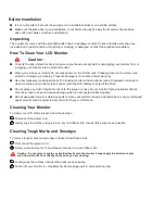
Страница 4: ...onitors and monitor screens can scratch the LCD display or strip off the finish Do not spray any kind of liquid directly onto the screen or case of your monitor Spraying liquids directly onto the scre...

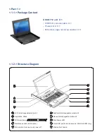
Страница 5: ...sher X 8 1 5 6 7 2 8 3 9 4 1 LCD interchangeable module kit 2 Installation Slides 3 LCD membrane 4 Membrane switch KVM option 5 Micro switch for screen auto power off 10 6 Keyboard interchangeable mod...

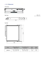
Страница 6: ...iew UNIT mm 1mm 0 03937 inch Top View Model Product Dimension W x D x H Packing Dimension W x D x H Net Weight Gross Weight KDX81712 441 6 x 580 x 44 mm 17 4 x 22 8 x 1 73 590 x 823 x 140 mm 23 2 x 32...

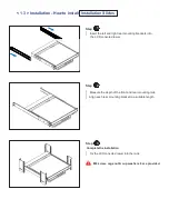
Страница 7: ...rear mounting brackets into the LCD console drawer Step 2 Measure the depth of the front and rear mounting rails Align each rear mounting bracket to a suitable length Step 3 Complete the installation...

Страница 8: ...ars before applying 2 post rack brackets Insert rear mounting brackets into the LCD console drawer Option Model MB 751 12 Step 2 Align each rear mounting bracket to a suitable length Step 3 Complete t...

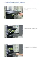
Страница 9: ...1 3 Installation How to use the drawer Hold the handle and slide out the drawer Flip up the LCD to a suitable angle Operate the LCD console drawer...

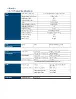
Страница 10: ...face hardness 3H Backlight Type LED MTBF hrs 20 000 Video Connectivity Digital DVI DVI D TMDS single link Audio Connectivity Audio Input Connector 3 5mm stereo jack Impedance Power level 30k 750mV Aud...

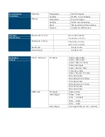
Страница 11: ...H 590 x 823 x 140 mm 23 2 x 32 4 x 5 5 inch Net Weight 15 kgs 33 lbs Gross Weight 19 kgs 42 lbs Applicable Format DVI D VGA Input PC Signal 1920 x 1200 x 60Hz 1920 x 1080 x 60Hz 1280 x 1024 x 60 75Hz...

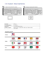
Страница 12: ...force 55 5g Travelling distance 3 0 3mm Switch life 10 million life cycle time Software support MS Windows 7 2008 2003 2000 XP ME 98 DOC Linux Mac Supporting layouts America EMEA Asia United States Un...

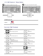
Страница 13: ...g layouts America United States How to Use MAC Keyboard Keyboard Features F1 Decrease display brightness F2 Increase display brightness F3 Mission control Only works with OS X Lion default Keyboard Sh...

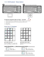
Страница 14: ...pose Copy and Help 104 keynotepad keyboard with full numerical pad and SUN function USB interface US layout only How to Use S Keyboard Num LED in Off mode Key pad behaves as a SUN Solar system adminis...

Страница 15: ...tons will automatically turn off after 10 minutes of idle status except the Power 2 Light up all membrane buttons please press any button for 1 2 seconds except the Power 1 Picture Picture mode Standa...

Страница 16: ...Adjust the volu me of sou nd Bass Set the value of bass sound Treble Set the value of treble sound Balance Set the balance value of treble and bass sound Analog TV audio Set the value of analog TV au...

Страница 17: ...ottom left top right bottom right OSD Menu MISC PIP Position top left top right bottom left bottom right top left top right bottom left bottom right Size Adjust the size of the Sub screen Large Small...

Страница 18: ...isplay the Sub screen next to the Main screen OSD Menu MISC PIP Mode PBP Main screen Sub screen Size LCD Monitor Main Sub screen 1920 x 1200 955 x 716 1920 x 1080 955 x 716 1440 x 900 715 x 536 1366 x...

Страница 19: ...g Input voltage 12 Volt 24 Volt 48 Volt Input range 9 18V 18 36V 36 75V Input current No load 50 mA 50 mA 50 mA Full load 4950 mA 2450 mA 1220 mA Output rating Output voltage 12 Volt 12 Volt 12 Volt O...

Страница 20: ...tion USB Servers DVI D KVM port Power Audio 6 5 4 3 2 1 USB Servers DVI KVM Cable 6 feet DVI KVM cable 15 feet DVI KVM cable Server end DVI D USB Audio KVM port DVI D USB3 0 IP console remoteconsole d...

Страница 21: ...keyboard hotkey Compatibility Multi platform Mix PCs SUN and Mac G3 G4 Mac iMac Support Windows 7 Vista 2003 XP Linux Unix Power Input 100 or 240V AC at 50 or 60 Hz via IEC type cord Option DC 12V 24...

Страница 22: ...N sequence is monitor KVM switch finally computer Front Panel Port LED Indications DVI D KVM 12 ports PC port LEDs Channel button Button B is non functional PC port LEDs Online Blue LED on indicating...

Страница 23: ...fic port Scroll Lock Scroll Lock S Auto scan for powered on PC Scroll Lock Scroll Lock B Enable Disable beeper sound Remarks Example of Scroll Lock Scroll Lock Port no Port No 01 to 12 e g Port 4 Scro...

Страница 24: ...Volt 24 Volt 48 Volt Input range 9 18V 18 36V 36 75V Input current No load 50 mA 50 mA 50 mA Full load 4950 mA 2450 mA 1220 mA Output rating Output voltage 12 Volt 12 Volt 12 Volt Output current 4 16...

Отзывы: