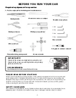
background image

H

G

B

D

C

E

I

J

-3-

2. CHARGING YOUR VEHICLE

Charge your vehicle's battery pack. Connect the charger in the box to your battery pack(it will only plug in 

one direction) and then plug the charger into a standard wall outlet. Charging takes approximately 2-3

hours. When the battery is fully charged, unplug the charger and connect the battery to your speed 

control.

Your vehicle charger will safely charge your battery pack and not over charge it. Be careful when using 

after market chargers that you do not overcharge the battery pack and ruin it.

By the way, this charger is only for the vehicle, not for the radio control. 

3. ASSEMBLING THE ANTENNA

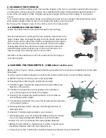
Locate the plastic antenna tube(found inside the manual bag).

Run the antenna wire up through the rear antenna mount hole in the 

upper chassis plate and begin feeding it into the plastic antenna tube

until it comes out the other side. Pull the remaining wire through the 

tube, and then press the tube into the antenna mount in the upper 

chassis plate. Bend the antenna wire down around the tube and

install the black rubber antenna cap on the top of the tube. You

may then wrap the remaining wire arount the tube.

DO NOT cut the antenna wire off! This could shorten the range of 

your radio system.

4. LEARNING THE TRANSMITTER -  AM(Brushed version use)

Before turning on your vehicle, please familiarize yourself with the controls and adjustments of the radio 

transmitter.

You may use the following diagram to confirm the location and function of each of these features.

A. ON/OFF Switch: Controls power to the transmitter.
B. Steering Wheel: Steering the vehicle left and right.
C. Throttle Trigger: Contols the speed and the Forward/Reverse

    direction of the vehicle.
D. Throttle Trim: Ajusts the neutral position of the throttle so 

    your vehicle responds correctly to the trigger.
E. Steering Trim: Adjusts the neutral position of the throttle so 

    your vehicle travels straight.

F. Throttle Reverse Switch: Reverses the forward/reverse direction

   of the steering wheel.

G. Steering Reverse Switch: Reverse the left/right direction of

    steering wheel.
H. Antenna: Transmits radio signals to your receiver.
I.  Recharging Jack: you can charge the battery with your charger

    if you are using rechargeable batteries in your transmitter.

Caution: You can not recharge Non-rechargeable batteries.

J. Battery Power Indicators: Signal when it is time to replace your

   transmitter batteries when the red indicator lit up.

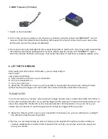
L. Frequency Crystal: Controls the operating frequency(channel) of your transmitter.

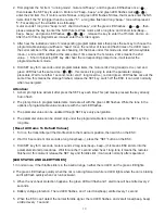
Содержание A2033T FLASH

Страница 1: ...ENT OF ESC MOTOR AND BATTERY CASUALLY WELL WE HAVE ATTACHED SEVERAL EQUIPMENTS PLEASE REFER TO THE DETAILED PARTS LIST WE WILL NOT TAKE ANY CHARGE OF THE DAMAGES OR INJURIES CAUSED BY YOUR CHANGES ASSEMBLE THIS KIT ONLY IN PLACES OUT OF CHILDREN S REACH TAKE ENOUGH SAFETY PRECAUTIONS PRIOR TO OPERATING THIS MODEL YOU ARE RESPONSIBLE FOR THIS MODEL S ASSEMBLE AND SAFE OPERATION A2033T FLASH V1 for ...

Страница 2: ... on all scews that work loose PLEASE READ BEFORE STARTING Thank you for selecting our racing product This vehicle is designed to be fun to drive and uses good quality parts for durability and performance The instruction manual you are reading was designed to be easy to follow yet thorough in its explanations We want you to enjoy driving your new R C car Well before you throw down this manual and u...

Страница 3: ...e who is not expecting it so it is extremely important to ALWAYS keep a safe distance between any people and the path of your vehicle don t forget this includes yourself Never run your vehicle through puddles wet grass snow or any other type of moisture Also never use any liquid cleaners around the electronic components on your vehicle Any small amount of moisture can cause severe damage to your e...

Страница 4: ...he tube DO NOT cut the antenna wire off This could shorten the range of your radio system 4 LEARNING THE TRANSMITTER AM Brushed version use Before turning on your vehicle please familiarize yourself with the controls and adjustments of the radio transmitter You may use the following diagram to confirm the location and function of each of these features A ON OFF Switch Controls power to the transmi...

Страница 5: ...ency crystals in your transmitter and receiver so that you can run together at the same time without causing any radio interference Additional frequency cystal sets can be purchased separately and installed in a few quick seconds While if you have our optional radio control system 2 4G at hand please read as following LEARNING THE OPTIONAL TRANSMITTER 2 4G You may use the following diagram to conf...

Страница 6: ...tter on C Turn your vehicle on D Adjust the ThrottleTrim knob on your transmitter if necessary if the wheels are moving forward without touching the trigger turn the throttle trim counter clockwise untill the wheels stop PLEASE NOTE If you do not have any reverse when pusing the trigger forward twice adjust the throttle trim further in the counter clockwise direction If you pull the trigger all th...

Страница 7: ...e switch off the ESC and then switch it on again to get the neutral point Functions Warning Forward push the throttle on the radio for gun type radio This ESC is not water proof Water trigger the throttle the car goes forward should be avoided If water goes into it take down the power switch Brake put the throttle to REVERSE to brake the car and use a blower to dry the ESC at meduim temperature th...

Страница 8: ...sion 32 30 31 5 with fan BEGIN TO USE THE NEW ESC Switch off the ESC connect the ESC motor receiver battery and servo as the attached diagrams Then turn on the transmitter Throttle Range Settings In order to make the ESC fit the throttle range you must calibrate it when you begin to use a new ESC or a new transmitter or change the settings of neutral position of the throttle stick ATV or EPA param...

Страница 9: ...Reverse Force 20 40 60 80 100 3 Brake Force 25 50 75 100 4 Drag brake force 0 10 20 40 70 100 5 Neutral range 3 6 9 12 6 Start mode Very fast fast normal slow 7 Timing 0 5 10 15 20 8 Battery voltage protection Ni xx no protection Li xx 2 8V cell Li xx 3 0V cell Li xx 3 2V cell Li xx 3 4V cell 9 Over heat protection 90 110 No protection 10 Protection mode lower power Cut off the main power immediat...

Страница 10: ...n the neutral position but no output 6 Start Mode It refers to the start force of ESC you can choose different start mode according to the road condition the tyre s ability to grip and etc 7 Timing The timing item is usable for sensorless brushless motors There are many differences among structures and parameters of different brushless motors so a fixed timing ESC is difficult to compatible with a...

Страница 11: ...ce at the same time this means the storage finished release the SET key switch off the ESC it can work normally when re energized Attention 1 A short prompt tone will emit after press the SET key each time This just means pressed the key already but no flash 2 The prompt tone in programmable items mode are all with the green LED flashes While the tone in the options of programmable value mode are ...

Страница 12: ...inal wires of the battery it is necessary to cut each wire seperately ensuring the wires not to touch each other Avoid pressing the battery while connecting disconnecting to the equipment never dsitroy the outside of the battery or bring the battery into contact with the sharp and hard odjects or else lead to leaking balloon short circuit even fire Dispose the used or damaged Li Po batteries at an...

Страница 13: ...ivers So here we declaration as below 1 Please do note this manual carefully especially the attentions parts and if you are a new player without enough experience we will not take any responsibility for the car damages or injuries caused by incorrect operation 2 Please do not change the matches of the brushless ESC motor and the Li Po battery casually if you want to make a change please do ask for...

Страница 14: ...424 30075 30067 33362 33341 33287 33286 33292 33416 30084 33291 33292 30026 30075 33280 33280 30067 33423 33269 33288 30073 33289 33290 33323 33269 30073 30073 30073 33293 33294 30832 30995 30026 washer is for adjusting further adjustments can be allowed according to the actual gap 33341 12 30026 33362 33371 33424 ...

Страница 15: ...3 Plastic shock components 3 Plastic shock components 4 Plastic shock assembly 4 Plastic shock assembly 30052 33487 33369 33285 33284 30406 14 33488 ...

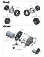
Страница 16: ...Tire assembly 6 Motor mounting 6 Motor mounting 32726 32178 33417 33288 33268 33295 33268 30085 33295 B1134 Brushless or B1147 Brushed 33491 15 33480 33486 33003 33492 33002 33480 33003 Or Or 33419 hop ups 33418 hop ups ...

Страница 17: ...ervo saver assembly 7 Servo saver assembly 8 Servo mounting 8 Servo mounting 33271 33267 33271 32880 33271 33304 33303 33271 33271 33267 33267 33277 30099 30099 33166 33271 33267 B1026 16 32726 32726 33166 ...

Страница 18: ...1 33271 33271 33271 33271 33271 30083 33274 33274 33275 33275 33275 33275 33275 33276 33276 33276 33276 33277 33277 33277 33277 33277 33277 33295 33295 33295 33295 33296 33296 33296 33296 33485 33297 33297 33297 33297 30809 33299 33300 33301 33301 33301 33302 33432 33306 33433 33308 33308 30816 33491 32726 32726 32726 32726 32785 30240 32785 32785 33320 33320 33487 B1112 brushless use 30095 B1146 ...

Страница 19: ... 33271 33271 33271 30083 33274 33274 33275 33275 33275 33275 33275 33275 33275 33276 33276 33276 33277 33277 33277 33277 33277 33277 33295 33295 33295 33295 33296 33296 33296 33296 33485 33297 33297 33297 33297 33299 33300 33301 33301 33301 33302 33306 33308 30816 32726 32726 32726 32726 32785 30240 32785 32785 33320 33320 33479 B1112 30095 B1146 19 20 33346 33347 33347 33347 33222 33484 30240 300...

Страница 20: ...0838 BM2 5 6 BH screw 10pcs 30995 ISO2 5 8 FH screw 10pcs 32178 Hexagon socket cap head screws M3 0 6L 32614 shock sleeve 6pcs 32616 ball head pad 32726 shock washer φ3 2 φ7 0 0 5 10pcs 32785 TPF3 10 FH screw 10pcs 32802 shock sleeve 2pcs 32880 washer ø3 3 ø8 0 8 10pcs 32916 BM3 22 BH screw 10pcs 32917 BT3 20 BH screw 10pcs 32958 TPF3 8 FH screw 10pcs 33002 rear tire 2pcs 33003 inner sponge 33156 ...

Страница 21: ... 5 3 5 BH screw 10pcs 33296 ball stud A Long 6pcs 33297 ball stud B short 6pcs 33299 pin φ3 34 for front susp arms 33300 pin φ3 44 for rear susp arm 2pcs 33301 tie rod M3 49 2pcs 33302 linkage plate for front susp Arm 33303 Steering axle sleeve core 33304 Translation sleeve shaft core 33306 front wheel shaft 2pcs 33308 wheel shaft pin φ2 0 11MM 10pcs 33309 pin φ3 31 for rear bearing seat 4pcs 3332...

Страница 22: ... B1006 50A ESC 33342 steering knuckle arms L R 33343 bearing seat L R 33344 C hub L R 33345 front susp arm seat 1pcs 33346 wheel hub 4pcs 33347 rear shock tower mount with BM3 12 BH screws 33348 rear susp Arm seat A B 33360 servo saver completed 1pcs 33361 battery cover glass fiber 1 30295 ball bearing 33372 front susp Arms 33373 rear susp arms L R 33418 motor pinion gear 11T with screw 33419 moto...

Отзывы: