background image

M T U   I n s t a l l a t i o n   G u i d e l i n e s

19

W

IRING

All wiring must be consistent with the wiring provided with the MTU and adhere 
to local and national codes.

Cable Insulation

Most MTUs are shipped with black cable insulation. Dual port MTUs, however 
will have two cables: one with black insulation and one with gray insulation. The 
black inulated cable is for port 1, and the gray insulated cable is for port 2.

Wire Length

MTUs are provided with a standard wire length of 12 feet. If necessary, additional 
wire may be used to extend the range between the meter and the MTU up to 500 
feet. (Some meters require shorter wire lengths. Please refer to the meter 
manufacturer’s documentation for exact limitations.) Always use cable of with 22 
AWG solid copper wire, preferably with similar insulation coloring when 
extending the wiring.

Wire Routing

All wiring should be secured every 18 inches and before and after every change in 
direction. Wiring routed along wood or drywall should be secured with 9/16" 
rounded-crown staples. Wiring routed along masonry walls should be secured 
using appropriate wire clips. The MTU cable should be allowed to move slightly 
within the staples or wire clips.

All changes in wire direction should only be made at right angles. Wiring should 
run parallel to ceiling joists, when possible. If joists must be crossed, the wiring 
should cross the joists at right angles.

If wire clearance holes are needed to route wire from the meter to the MTU, use a 
¼" drill bit. The installer is responsible for the selection of an appropriate location 
for any hole to be drilled.

Содержание MTU

Страница 1: ...ritten authorization of Aclara Any software or firmware described in this document is furnished under a license and may be used or copied only in accordance with the terms of such license DISCLAIMER T...

Страница 2: ......

Страница 3: ...loyment Process 1 Recommended Equipment 2 Signal Propagation 3 Free Space Attenuation 4 RF Absorption 4 RF Reflection 5 RF Shadowing 6 Mounting Considerations Exterior Mounting 9 Interior 14 Pit 17 Wi...

Страница 4: ...ii M T U I n s t a l l a t i o n G u i d e l i n e s Table of Contents...

Страница 5: ...exposure guide and the field calibration procedure FCC IC RF Exposure Guide Aclara Technologies LLC low power RF devices and their antennas must be fixed mounted on indoor or outdoor permanent structu...

Страница 6: ...iv M T U I n s t a l l a t i o n G u i d e l i n e s FCC IC Compliance...

Страница 7: ...ion Support The Aclara Customer Portal http customer aclaratech com provides a wide range of information that can serve as a starting point when you have a question If at any time you would like to sp...

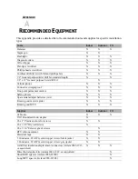
Страница 8: ...8 x 1 3 4 exterior screws Hammer Flashlight Diagonal cutters Wire stripper Drill bits 6 x 1 5 8 drywall screws Cordless drill Screwdrivers and screwdriver bits Silicone gel filled electrical insulati...

Страница 9: ...commended intallation guidelines may create conditions that exceed the limits of the STAR Network All devices that operate in the UHF band are considered to use line of sight transmission and operate...

Страница 10: ...e actual installation of the MTU will not change the free space attenuation considerably certain locations may require the use of an extended range MTU or an increase in the number of DCUs to improve...

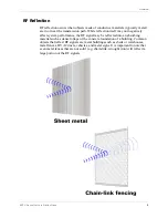
Страница 11: ...vely affect system performance the RF signal may be reflected into an absorbing material such as dense foliage or the concrete foundation of a building Common objects that reflect RF signals are metal...

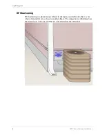
Страница 12: ...gnal Propagation RF Shadowing RF shadowing is a phenomenon related to absorption and reflection that occurs when a transmitter is too close to another object The image below illustrates how the downsp...

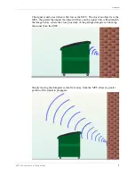
Страница 13: ...ser an object is to the MTU the greater the impact the object will have on the signal This is illustrated in the image below where the close proximity of the garbage dumpster is blocking the signal fr...

Страница 14: ...8 M T U I n s t a l l a t i o n G u i d e l i n e s Signal Propagation...

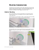
Страница 15: ...t the MTU must be mounted securely Exterior Mounting Issues with performance of exterior mounted MTUs are typically the result of mounting the MTU too low or mounting it in such a way that it is block...

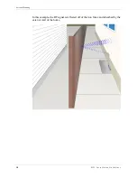
Страница 16: ...10 M T U I n s t a l l a t i o n G u i d e l i n e s Exterior Mounting In this example the RF signal is reflected off of the iron fence and absorbed by the exterior wall of the home...

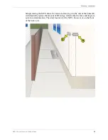
Страница 17: ...l i n e s 11 Simply raising the MTU above the fence and moving it to the end of the home B will drastically reduce the amount of RF energy reflected by the fence and improve system communication The i...

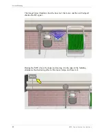
Страница 18: ...terior Mounting The image below illustrates how the hose reel the meter and the wall ledge all shadow the RF signal Raising the MTU above the ledge and moving it to the edge of the building eliminates...

Страница 19: ...om any metal objects including pipes conduit and downspouts Mount the MTU so that the top is at least one inch below the siding overlap When mounting multiple MTUs in the same location leave at least...

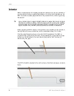
Страница 20: ...to entering the building and then again at the proposed mounting location A drastic drop in cellular signal reception may indicate potential problems with MTU transmission When mounting an MTU inside...

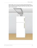
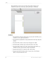
Страница 21: ...s 15 Mount the MTU at least 5 10 feet away from large metal objects like furnaces duct work refrigerators and cabinets In the example below the MTU is mounted between the HVAC duct and the refrigerat...

Страница 22: ...e ground level Mount the MTU perpendicular to the ground with the Aclara logo facing the installer Mount the MTU at least six inches away from pipes and conduit Mount the MTU so that the top is severa...

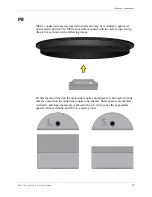
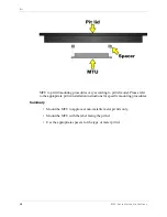
Страница 23: ...MTUs should be mounted with the Aclara logo facing the pit lid as shown in the following image Pit lids that are ribbed on the underside require short spacers while meter pit lids that are smooth on t...

Страница 24: ...ccording to pit lid model Please refer to the appropriate pit lid installation instructions for specific mounting procedures Summary Mount the MTU to approved non metallic meter pit lids only Mount th...

Страница 25: ...r exact limitations Always use cable of with 22 AWG solid copper wire preferably with similar insulation coloring when extending the wiring Wire Routing All wiring should be secured every 18 inches an...

Страница 26: ...manufacturer s instructions Please consult the appropriate meter installation instructions for specific MTU wiring instructions Interior Exterior Environment All wire connections outside the building...

Страница 27: ...r crimping tool X X X Fine point permanent marker X X X Safety glasses X X X Spare serial adapter batteries AA X X X Known good meter register X X X Known good MTU X X X Supplies Indoor Outdoor Pit Ca...

Страница 28: ...22 M T U I n s t a l l a t i o n G u i d e l i n e s...

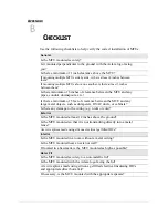
Страница 29: ...he MTU and any large metal objects such as dumpsters HVAC ducts or cabinets Is there any damage to the wiring e g nicks or cuts Exterior Is the MTU mounted at least 12 inches above the ground Is the M...

Страница 30: ......
Отзывы: