background image

-5- 


TROUBLESHOOTING


None of the LED indicators turn ON 

  Verify the power supply (voltage, cabling). 

  Verify the fuse “FUS” on the back of the evaluation board. 


The ETHERNET link/activity led indicator stays OFF 

  Check the Ethernet plugs. Use the provided RJ45 cable. 

  Check that the peer device is working properly. 

  Try to connect another device. 


The Wi-Fi link does not come up 

  Make sure that the Wireless parameters  of the Client  (case sensitive 

SSID, 802.11 mode, radio channel and security) match those of the AP. 

  Check the radio conditions: distance between devices, placement of 

antennas, interferences and obstacles to radio waves propagation. 

  Try with all securities and encryption settings temporarily disabled. 

  Try using the product with factory settings as shown in the “Quickly 

evaluate…” section. 

  Try another radio channel. 


How to restore factory settings? 

  If the built-in web-based interface is reachable, you can use a browser 

to restore factory settings. 

  Else, power up the unit, wait for the red “Diag” LED to turn green, then 

hold down the reset button (for at least 2 seconds) until “Diag” goes red. 
Then release it and wait for the Diag LED to turn green again, meaning 
that the product rebooted with its factory settings. 

CONNECTORS


RJ45 Ethernet connector 

The Ethernet port is auto-sensing and self-configuring (auto-MDI/MDIX) to 
allow connection to either a crossover or straight-through connector.


Power supply Jack connector 12 V       (J13) 

The product can be powered by any 12VDC power supply (minimum 1A). It 
handles polarity inversions. 
 

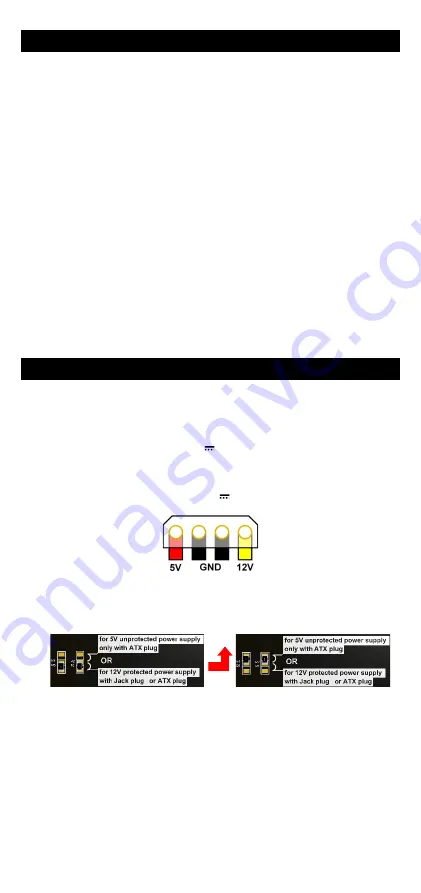
Power supply Molex connector 5/12 V       (J12) 


The product can be powered by an ATX 12V power supply (mini 1A) 
If necessary, it could be also powered by 5V (mini 2.5A). To allow this, you 
need to move R5/R1 resistors towards R4/R2 positions. 

WARNING

: In this 

case the product is neither short-current protected nor polarity protected. 


WARNING: The product must be powered by only one source. Do not 
use both power connectors together. 
 

Serial port connectors UART0 and UART1 

UART0 is reserved for use by ACKSYS. UART1 is meant for programming 
firmware extensions. Contact Acksys for more information. 


Содержание EmbedAir Series

Страница 1: ...et un acc s internet pour installer les derni res MAJ un navigateur IE ou compatible Copyright 2018 par ACKSYS Selon la loi du 11 mars 1957 tout ou partie du pr sent document ne pourra tre reproduit s...

Страница 2: ...lon le tableau ci dessous Ant 1A sur TX0 Ant 1B sur TX1 Ant 2A Main sur CH0 ou MAIN Ant 2B Aux sur CH1 ou DIV Ant 2C GNSS sur CH2 ou GNSS 4 Installer l EmbedAir sur la carte EmbedAir CB en l emboitant...

Страница 3: ...site web d ACKSYS Passez directement l tape 5 si l adresse par d faut du produit est compatible avec votre r seau S lectionnez votre quipement et cliquez sur Configurer Vous pouvez alors configurer l...

Страница 4: ...nfigur e en Point d acc s o SSID acksys diffus o Aucune s curit Ni WEP ni WPA ni WPA2 aucun filtrage MAC o Mode 802 11n ou ac Canal auto Mise en uvre rapide des modes bridge et AP M thode pour essayer...

Страница 5: ...non mettez le produit sous tension attendez la fin d initialisation et maintenez le bouton reset appuy au moins 2 secondes jusqu au passage du voyant Diag en rouge Rel chez et attendez qu il repasse e...

Страница 6: ...GNSS Vert Eteint Carte radio d sactiv e Clignotant Recherche de position Allum fixe Position tablie ETHERNET LINK Vert Allum Liaison Ethernet tablie Clignotant Envoi R ception de donn es SPEED Jaune...

Страница 7: ...mode emergency upgrade Alimentation Caract ristiques DC 12V 5 avec fusible r f 0154001 DR et protection contre les inversions de polarit DC 5V 5 sans fusible ni protection Connecteurs Jack 2 1mm Molex...

Страница 8: ...8 Page Blanche...

Страница 9: ...IE or compatible Copyright 2018 by ACKSYS Under the law of march 11 1957 the reproduction in whole or in part of this work by any means whatsoever is prohibited without the prior written consent of A...

Страница 10: ...Connect the UFL connectors to the radio according to the information below Ant 1A to TX0 Ant 1B to TX1 Ant 2A Main to CH0 or MAIN Ant 2B Aux to CH1 or DIV Ant 2C GNSS to CH2 or GNSS 4 Take the EmbedAi...

Страница 11: ...efault IP address is compatible with your network Else select the device and click on the Configure button You can configure the IP address or you can activate the DHCP client 4 Device configuration C...

Страница 12: ...2 no MAC filter o 802 11n or ac mode 5GHz band auto channel QUICKLY EVALUATE AP BRIDGE MODES Quickly evaluate the ACKSYS device in AP role You need a second computer PC2 with a working Wireless connec...

Страница 13: ...power up the unit wait for the red Diag LED to turn green then hold down the reset button for at least 2 seconds until Diag goes red Then release it and wait for the Diag LED to turn green again mean...

Страница 14: ...GNSS Green Off The radio is disabled Blinking Position search Solid On Position established ETHERNET LINK Green On Link on LAN established Flashing Tx Rx activity SPEED Yellow Green Yellow Connected...

Страница 15: ...nter emergency upgrade Power supply Input Specifications DC 12V 5 with fuse ref 0154001 DR and polarity protection DC 5V 5 w o fuse and protection Connector Jack 2 1mm Molex 15 24 4441 type 8981 4M Ex...

Страница 16: ...8 White page...

Отзывы: