


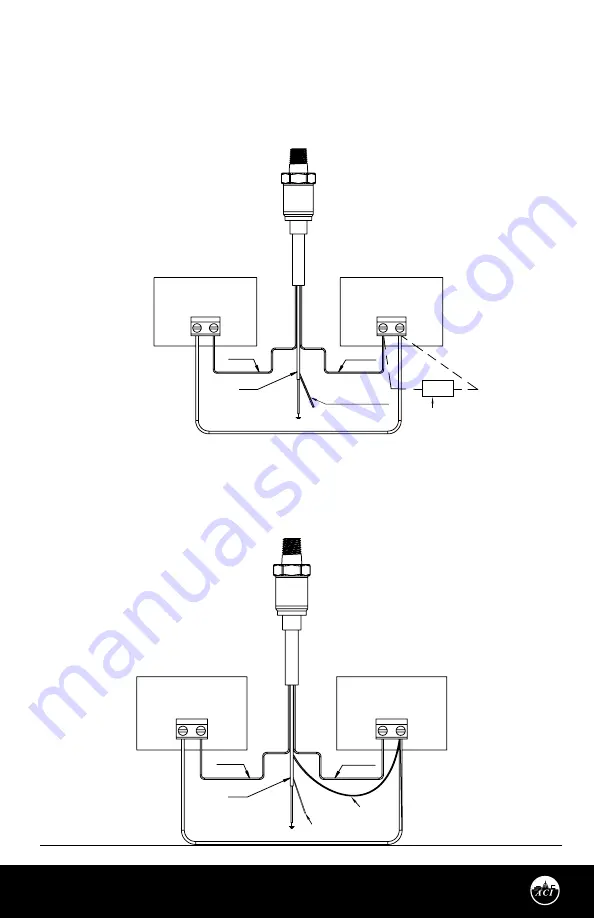
FIGURE 3:
CURRENT WIRING
DIAGRAM
Automation Components, Inc.
2305 Pleasant View Road | Middleton, WI 53562
Phone:
1-888-967-5224 |
Website:
workaci.com
Page 3
Version: 3.0
I0000792
MEDIA COMPATIBILITY
The bulk micro-machined transducer features a stainless steel diaphragm with welded construction that
contains no O-rings, which makes them compatible with any gas or liquid that’s compatible with 304L or
316L stainless steel. Some compatible gasses and liquids include refrigerants, glycol, motor oil, diesel,
hydraulic fluid, brake fluid, water, waste water, hydrogen, nitrogen and air.
Installation
LOCATION
Install the sensor in a location where it will not be exposed to extreme temperatures, vibration or shock.
Install the pressure sensor above or on the side of pipes, in a location where liquid will not drip on the unit.
Condensation can potentially build up and run down the harness; position the unit and harness so water
does not pool on the back of the sensor. Do not install the sensor at the end of a long run of pipe.
CONNECTION
The P51 series sensor is available with multiple
external thread sizes, see the Datasheet chart
for more details. Standard pipe fittings and
installation procedures should be used during
installation. Install pipe tape, thread sealant or
other suitable pipe compound when
connecting the sensor to the pressure source or
any of the accessories. For pressure ranges
more than 500 PSI (3447.4 kPa), we recommend
the use of a sealant such as Loctite Hydraulic
Sealant. Do not use excessive amounts of
sealant or you might block the pressure going
into the transducer. Install the device using a
wrench on the hex flats provided. Do not use a
strap wrench on the body. When installing the
sensor, the torque limit will vary, see the Torque
Limits Table for more detail. Do Not over
tighten. Overtightening metal fittings may
cause a slight zero shift. The use of plastic
fittings typically results in no noticeable zero
shift. The torquing effect does not appreciably
affect linearity or sensitivity. In liquid pressure
monitoring applications, air present in the lines
will cause erratic readings, use bleed fittings to
bleed off any air that has been trapped before
transducer installation.
WIRING INSTRUCTIONS
The supply voltage and current required will
vary per unit, see the General Specifications
Table for more details. If you’ve selected a Packard connector make the proper connections to the harness,
then install the P51 Sensor onto the harness.
Note:
Be careful not to kink the vent tube if cutting the 24” PVC wire down or removing all together.
Kinking the clear tube will affect the reference pressure on all PSIG Series Transducers.
4-20 OUTPUT CONNECTIONS
Connect the Power lead (Red) to the plus terminal of the supply voltage. Connect the Return lead (White)
WIRING INSTRUCTIONS
(Continued)
to the plus terminal of the current measuring device (controller). Connect the minus terminal of the
current measuring device to the minus terminal of the supply voltage, and the Shield Wire (Green) should
be connected to the system or earth ground. See
Figure 3
, Current Wiring diagram.
Note:
If the harness has a black wire, do not use it.
COM
RED WIRE
WHITE WIRE
CLEAR VENT TUBE
Clear Vent Tube on
I24 Lead Style Only
Optional 250 Ohm or 500 Ohm
Load Resistor for a 1-5 VDC or
2-10 VDC Output
SHIELD
POWER SUPPLY
+13 TO 30 VDC
- +
AUTOMATION
PANEL
AI1
FIGURE 4:
VOLTAGE WIRING
DIAGRAM
COM
RED WIRE
WHITE WIRE
BLACK WIRE
Note:
Clear Vent Tube on
I24 Lead Style Only
AI1/AI2 = VDC
Analog Input
CLEAR VENT TUBE
SHIELD
POWER SUPPLY
+5 TO 30 VDC
- +
AUTOMATION
PANEL
AI1
VOLTAGE OUTPUT CONNECTIONS
Connect the Power lead (Red) to the plus terminal of the supply voltage. Connect the Ground lead (Black)
and the minus terminal of the supply voltage to the minus input of your voltage measurement equipment.
Connect the Vout lead (White) to the plus input of your voltage measurement equipment, and the Shield
Wire should be connected to the system or earth ground. See
Figure 4
, Voltage Wiring diagram.