


3
that takes commands from the Remote Control is
located here. Do not obstruct line of sight access to
this portion of the display during use.
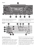
15. INFORMATION DISPLAY WINDOW – This
color display shows a range of information, as well as
the frequency levels of the program material.
1
2
3
4
5
6
7
8
9
12
13
10
14
15
Back Panel Operations
Refer to the Figure B directly above.
1. MICROPHONE INPUTS – These two 1/4" jacks
are alternate, back-panel inputs for Mic 1 and Mic 2.
Use front panel knobs to control volume and tone.
2. VIDEO INPUTS – This line of Video inputs that
take RCA connectors from the various source inputs.
Each Video input is associated with the Left and
Right Audio inputs directly below (see Item #3, below).
3. AUDIO – These Audio inputs, Left and Right, ac-
cept source inputs (BGM, AUX, DVD and CDG).
4. PRE – These RCA jacks allow you to send the sig-
nal to an external signal processor via the Ouput jacks,
and receive the processed signal back via Inputs.
5. VIDEO OUT – This RCA output jack works with
the Audio outs below it (see Item #6, below) to supply
a composite signal to an external device.
2
3
4
5
6
1
10 11
12
9
13
7
8
11
Figure B
Figure A


