


System Utilities
2-11
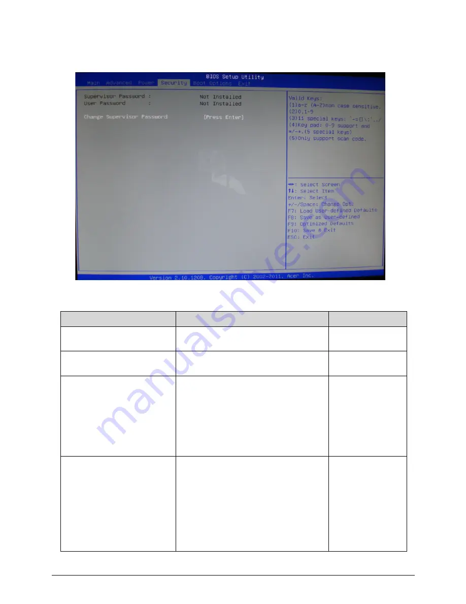
Security
0
Table 2-7.
Parameter
Description
Options
Supervisor Password:
Information only.
Not
Installed/Installed
User Password:
Information only.
Not
Installed/Installed
Change Supervisor Password
Valid Keys:
(1)a-z (A-Z) non case sensitive.
(2)0, 1-9
(3)11 special keys: ‘- = [] \ ; ‘ , . /
(4)Key pad: 0-9 support and */-+. (5
special keys)
(5)Only support scan code.
[Press Enter]
Change User Password
This item is available if supervisor
password is installed.
If clear supervisor password, user
password should also be cleared.
All setup items will be view-only except
user password item if login with user
password, the hot key F9 (load default
settings) is also not available to change
BIOS settings.
[Press Enter]
Содержание Veriton Z4621G
Страница 1: ...Acer VZ4620G VZ4621G SERVICEGUIDE ...
Страница 2: ...ii ...
Страница 6: ...vi ...
Страница 7: ...vii ...
Страница 8: ...viii ...
Страница 9: ...CHAPTER 1 Hardware Specifications ...
Страница 28: ...1 20 Hardware Specifications and Configurations M B Placement 0 ...
Страница 30: ...1 22 Hardware Specifications and Configurations Internal header pin definition 0 ...
Страница 31: ...Hardware Specifications and Configurations 1 23 Block Diagram 0 ...
Страница 32: ...1 24 Hardware Specifications and Configurations ...
Страница 33: ...CHAPTER 2 System Utilities ...
Страница 50: ...2 18 System Utilities 8 Flash BIOS is finished ...
Страница 53: ...System Utilities 2 21 8 Select Save Exit Setup and press Enter key 9 Select Yes and press Enter key ...
Страница 54: ...2 22 System Utilities 10 Flash BIOS is finished ...
Страница 57: ...System Utilities 2 25 7 Select Yes and press Enter key 8 Select Save Exit Setup and press Enter key ...
Страница 58: ...2 26 System Utilities 9 Select Yes and press Enter key 10 Flash BIOS is finished 0 With ME lock 0 ...
Страница 62: ...2 30 System Utilities 10 Select Yes and press Enter key 11 Select Save Exit Setup and press Enter key ...
Страница 63: ...System Utilities 2 31 12 Select Yes and press Enter key 13 Flash BIOS is finished ...
Страница 65: ...System Utilities 2 33 9 Select Yes and press Enter key 10 Select Save Exit Setup and press Enter key ...
Страница 66: ...2 34 System Utilities 11 Select Yes and press Enter key 12 Flash BIOS is finished ...
Страница 69: ...System Utilities 2 37 ...
Страница 73: ...System Utilities 2 41 ...
Страница 74: ...2 42 System Utilities ...
Страница 75: ...CHAPTER 3 System Disassembly and Assembly ...
Страница 78: ...3 4 ...
Страница 86: ...3 12 System Disassembly and Assembly First open one top side then open the other top side ...
Страница 87: ...System Disassembly and Assembly 3 13 Open the low side ...
Страница 96: ...3 22 System Disassembly and Assembly Removing the Display Card 0 ...
Страница 106: ...3 32 System Disassembly and Assembly Remove the heatsink in the direction as indicated by the arrow Removing the CPU 0 ...
Страница 113: ...System Disassembly and Assembly 3 39 ...
Страница 118: ...3 44 System Disassembly and Assembly Remove the base pan in the direction as indicated by the arrow ...
Страница 121: ...System Disassembly and Assembly 3 47 Unplug the LCD power cable Take out the LCD with bracket ...
Страница 128: ...3 54 System Disassembly and Assembly 4 Plug the LCD power cable NOTE NOTE Be careful that do not plug it on backward ...
Страница 131: ...System Disassembly and Assembly 3 57 Lock all the latch Plug the LVDS cable ...
Страница 132: ...3 58 System Disassembly and Assembly Screw 8 screws to fix it Table 3 28 ID Size Quantity Screw Type M3X5L B 8 ...
Страница 141: ...System Disassembly and Assembly 3 67 Close the CPU bracket cover ...
Страница 142: ...3 68 System Disassembly and Assembly Lock the latch in the direction as indicated by the arrow ...
Страница 143: ...System Disassembly and Assembly 3 69 Replacing the Memory 0 1 Instal the lower memory 2 Instal the upper memory ...
Страница 147: ...System Disassembly and Assembly 3 73 Lock 2 VGA locks ...
Страница 153: ...System Disassembly and Assembly 3 79 Attach the mylar to cover the camera ...
Страница 160: ...3 86 System Disassembly and Assembly 4 Attach the mylar as the location shown in the picture ...
Страница 164: ...3 90 System Disassembly and Assembly N A 4 Table 3 45 ID Size Quantity Screw Type ...
Страница 166: ...3 92 System Disassembly and Assembly Screw 9 screws to fix it Table 3 46 ID Size Quantity Screw Type M3X5L B 9 ...
Страница 170: ...3 96 System Disassembly and Assembly Install the hinge cover ...
Страница 171: ...System Disassembly and Assembly 3 97 Thermal Pad location on base pan 0 ...
Страница 174: ...3 100 System Disassembly and Assembly ...
Страница 175: ...CHAPTER 4 Troubleshooting ...
Страница 187: ...Troubleshooting 4 13 Following program s prompt in order as up right low left press the proper hole by using the stylus ...
Страница 190: ...4 16 Troubleshooting Pressing the 25 calibration points in proper hole by using the stylus ...
Страница 194: ...4 20 Troubleshooting ...
Страница 195: ...CHAPTER 5 Jumper and Connector Locations ...
Страница 196: ...5 2 Jumper Setting 5 4 Setting Jumper 5 4 ...
Страница 197: ...Jumper and Connector Locations 5 3 Jumper and Connector Locations ...
Страница 199: ...Jumper and Connector Locations 5 5 This illustration shows a 3 pin jumper Pins 1 and 2 are SHORT ...
Страница 200: ...5 6 Jumper and Connector Locations ...
Страница 201: ...CHAPTER 6 FRU List ...
Страница 202: ...6 2 VZ4620G VZ4621G Exploded Diagrams 6 4 FRU List 6 7 ...
Страница 204: ...6 4 FRU Field Replaceable Unit List VZ4620G VZ4621G Exploded Diagrams 0 Main Exploded Diagram ...
Страница 215: ...FRU Field Replaceable Unit List 6 15 SCREW M3 8 0L P B NI 2 86 U6N0U 005 Table 6 2 FRU list Category Description P N ...
Страница 216: ...6 16 FRU Field Replaceable Unit List ...


