


100
Chapter 4
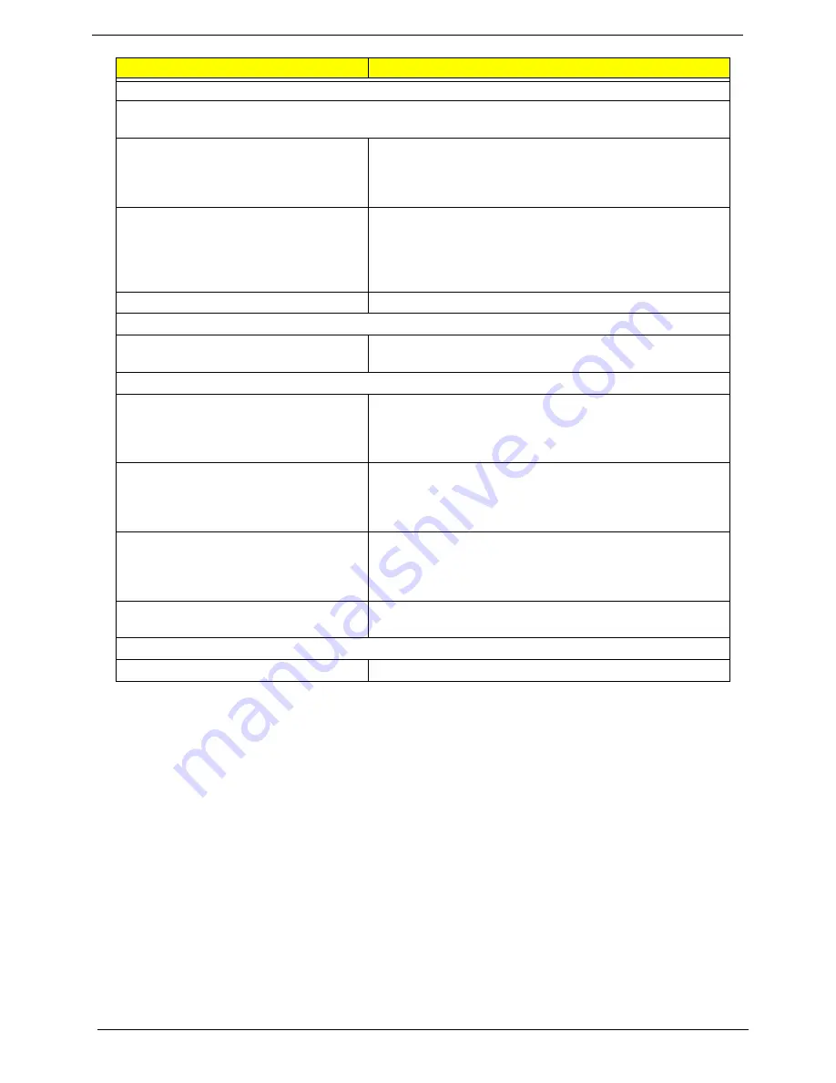
Parallel/Serial Ports
Execute “Load BIOS Default Settings” in BIOS Setup to confirm ports presence before diagnosing any
parallel/serial ports problems.
Serial or parallel port loop-back test
failed.
1. Make sure that the LPT# or COM# you test is the same
as the setting in BIOS Setup.
2. Loop-back.
3. Main board.
Printing failed.
1. Ensure the printer driver is properly installed. Refer to the
printer service manual.
2. Printer.
3. Printer cable.
4. Main board.
Printer problems.
1. Refer to the service manual for the printer.
Keyboard
Some or all keys on keyboard do not
work.
1. Keyboard
Power Supply
Pressing power switch does not turn off
system. (Only unplugging the power
cord from electrical outlet can turn off the
system.)
1. Ensure the
Soft-off by PWR-BTTN.
in BIOS Setup
of
Power Management
is not set to Instant-off.
2. Power switch cable assembly
Pressing power switch does not turn on
the system.
1. Ensure the power override switch (situated at the back of
the machine, just above the connector for the power
cable) is not set to OFF.
2. Power switch cable assembly.
Executing software shutdown from
Windows98 Start menu does not turn off
the system. (Only pressing power switch
can turn off the system).
1. Load default settings.
2. Reload software from Recovery CD.
No system power, or power supply fan is
not running.
1. Power Supply
2. Main board
Other Problems
Any other problems.
1. Undetermined Problems
Error Symptom
Action/FRU
Содержание Veriton 5900Pro
Страница 17: ...Chapter 1 11 Rear panel Veriton 5900Pro rear view Veriton 6900Pro rear view ...
Страница 24: ...18 Chapter 1 ...
Страница 34: ...28 Chapter 1 ...
Страница 42: ...36 Chapter 2 Total Memory Base Upper Extended Total Memory N A Parameter Description Options ...
Страница 73: ...Chapter 3 67 2 Detach the USB board with its upper bracket then pull out the USB audio cables ...
Страница 79: ...Chapter 3 73 2 Detach the ODD module from the chassis 3 Detach the card reader carefully ...
Страница 82: ...76 Chapter 3 4 Then remove the power supply from the chassis ...
Страница 90: ...84 Chapter 3 3 Remove the four screws holding the system fan 4 Detach the system fan ...
Страница 92: ...86 Chapter 3 4 Remove the screw fastening the LED module then detach the LED module ...
Страница 108: ...102 Chapter 4 ...
Страница 112: ...106 Chapter 6 Veriton 7900Pro Exploded Diagram ...
Страница 113: ...Chapter 6 107 Veriton 6900Pro Exploded Diagram ...
Страница 114: ...108 Chapter 6 Veriton 5900Pro Exploded Diagram 1 3 4 5 6 7 8 9 10 11 3 4 5 6 7 8 9 21 22 23 FAN60 60 25 ...
Страница 116: ...110 Chapter 6 ...


