


System Board
1-3
1.1.1
System Board
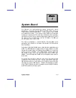
Figure 1-1 shows the locations of the system board major
components.
1
Battery
2
Tag SRAM
3
Pipeline burst second-level cache
4
Pentium CPU socket
5
CPU voltage regulators
6
SIMM sockets
7
Buzzer
8
Switch 2 (SW2)
9
Video RAM upgrade sockets
10
Video RAM
11
Video port
12
Parallel port
13
BIOS
14
Serial port 2
15
Slot board connector
16
Serial port 1
17
Mouse port
18
Keyboard port
19
USB connector
Figure 1-1
System Board Layout


