35
5. Power Board
No power
Check to CN902 Pin10,11 =14V and Pin6,7 = 5 V
OK
Check Interface board
Check AC line volt 120V or 220V
Change F901, Check BD901, L901, IC901
Check the voltage of C905(+)
Check bridge retified circuit
Check start voltage for the Pin2 of IC901
Change IC901
OK
Check the auxiliary voltage is smaller than 20V
OK
NG
No power
NG
NG
OK
Check T901,D906, D907, Q903,ZD921,ZD922,IC904,IC903
Check IC901
NG
OK
NG
Содержание V203W
Страница 1: ...1 Acer V203W Service Guide...
Страница 11: ...11 Electrical Characteristics TFT LCD Module Power Specification Backlight Unit...
Страница 12: ...12 Optical Specifications...
Страница 16: ...16 Software Flow Chart N Y 1 2 N Y 5 Y N 10 Y N 12 Y N 7 Y N 6 4 3 8 9 14 11 13 Y N 15 Y N 16 17 19 Y N 18...
Страница 22: ...22 eColor Management OSD...
Страница 23: ...23 How to Adjust a Setting...
Страница 24: ...24 Adjusting the picture...
Страница 25: ...25...
Страница 29: ...29 3 Remove the back cover and bezel Fig 3 Fig 3 4 Remove the lamp connectors and the screw Fig 4 5 Fig 4 Fig 5...
Страница 37: ...37 Connector Information The following figure shows the connector locations on the monitor Chapter 5...
Страница 40: ...40 4 Power Board 5 Main Board...
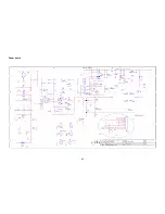
Страница 45: ...45 Power board...
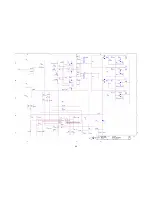
Страница 46: ...46...


