background image

1-48

Disassembly Procedures

Top Assembly Removal (Keyboard Removal)

0

Prerequisite: 

HDD SKU: Ensure that the USB Board, Speakers, HDD Module, Touchpad 
Module, and LCD Module have been disassembled prior removing the top 
assembly.

LTE and/or NFC SKUs: Ensure that the USB Board, Speakers, LTE Board, 
NFC Module, Touchpad Module, and LCD Module have been 
disassembled prior removing the top assembly.

NOTE:

NOTE

:

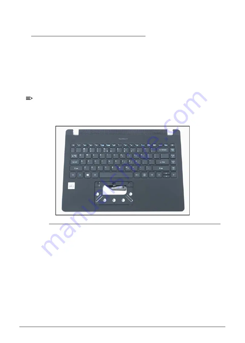
The keyboard is included as part of the top assembly and can not be disassembled. 
In the event that the keyboard can no longer be used, replace the entire top 
assembly.

Figure 1-67. Top Assembly (Keyboard)

Содержание TravelMate P2 Series

Страница 1: ...TravelMate P2 TMP214 52 TMP214 52G TravelMate P214 52 TravelMate P214 52G TMP40 52 TMP40 52G LIFECYCLE EXTENSION GUIDE...

Страница 2: ...i Disassembly Procedures 1 1 Troubleshooting 1 49 FRU Field Replaceable Unit List 1 50 Exploded Diagrams 1 51 Software Update 1 54 Personal Data Removal 1 55...

Страница 3: ...ourself by using a wrist grounding strap or by periodically touching an unpainted metal surface at the same time as touching a connector on the back of the computer Take off any metal objects on your...

Страница 4: ...ocedures WEEE Annex VII Component 0 These components are classified as requiring selective treatment Battery pack WLAN module DIMM modules SSD module LTE module Touchpad module USB board Mainboard RTC...

Страница 5: ...es 1 Place the system on a stable work surface 2 Remove AC adapter A from the system and peripherals Figure 1 1 3 Remove all cables from system Figure 1 1 AC Adapter Outlet 4 Remove the SD card from t...

Страница 6: ...the base cover Figure 1 3 Figure 1 3 Base Cover Removal 2 Carefully pry up the base cover starting from the upper side near the LCD hinges to release the latches Then continue releasing the remaining...

Страница 7: ...Disassembly Procedures 1 5 3 Grasp and remove the base cover from the system Figure 1 5 Figure 1 5 Base Cover Removal...

Страница 8: ...Base Cover Removal 1 Find the battery pack A in the system Figure 1 6 2 Detach the adhesive tape B from the battery cable connector Figure 1 6 3 Detach the transparent mylar C securing the fan and ba...

Страница 9: ...e from the mainboard connector D Figure 1 7 Figure 1 7 Battery Pack Removal 5 Remove the battery pack from the system Figure 1 8 Figure 1 8 Battery Pack Removal IMPORTANT Follow local regulations for...

Страница 10: ...le A on the top assembly Figure 1 9 Figure 1 9 WLAN Module Location 2 Disconnect the AUX antenna cable white color from the WLAN AUX pin Figure 1 10 3 Disconnect the MAIN antenna cable black color fro...

Страница 11: ...ne 1 screw securing the WLAN module in place Figure 1 10 Figure 1 10 WLAN Module Removal 6 Remove the WLAN module from the mainboard connector B Figure 1 11 Figure 1 11 WLAN Module Removal AUX MAIN B...

Страница 12: ...Battery Pack Removal 1 Find the WLAN module A on the top assembly Figure 1 12 Figure 1 12 WLAN Module Location 2 Disconnect the AUX antenna cable white color from the WLAN AUX pin Figure 1 13 3 Discon...

Страница 13: ...one 1 screw securing the WLAN module in place Figure 1 13 Figure 1 13 WLAN Module Removal 5 Remove the WLAN module from the mainboard connector B Figure 1 14 Figure 1 14 WLAN Module Removal AUX MAIN B...

Страница 14: ...bly Procedures DIMM Modules Removal 0 Prerequisite Battery Pack Removal 1 Find the DIMM module A in the system Figure 1 15 2 Push the DIMM module clips B outwards Figure 1 15 Figure 1 15 DIMM Module R...

Страница 15: ...dures 1 13 3 Remove the DIMM module from the mainboard connector C Figure 1 16 Figure 1 16 DIMM Module Removal 4 Repeat steps 2 and 3 for an additional DIMM module if necessary C WEEE Annex VII DIMM M...

Страница 16: ...e Battery Pack Removal 1 Remove one 1 screw securing the SSD module A in place Figure 1 17 Figure 1 17 SSD Module Removal 2 Remove the SSD module from the mainboard connector B Figure 1 18 Figure 1 18...

Страница 17: ...module A on the top assembly Figure 1 19 2 Disconnect the MAIN antenna cable yellow color from the LTE MAIN pin Figure 1 19 3 Disconnect the AUX antenna cable blue color from the LTE AUX pin Figure 1...

Страница 18: ...1 16 Disassembly Procedures 5 Remove the LTE module from the mainboard connector B Figure 1 20 Figure 1 20 LTE Module Removal B WEEE Annex VII LTE Module Component...

Страница 19: ...isite Battery Pack Removal 1 Disconnect the WLAN antenna cables B from the WLAN module connectors Figure 1 21 2 Detach the adhesive tape A from the mainboard Figure 1 21 3 Remove four 4 screws C secur...

Страница 20: ...Procedures 4 Remove the HDD module assembly D from its compartment Figure 1 22 Figure 1 22 HDD Module Removal 5 Disconnect the HDD cable from the HDD module connector E Figure 1 23 Figure 1 23 HDD Mo...

Страница 21: ...Disassembly Procedures 1 19 6 Remove four 4 screws F from the HDD bracket Figure 1 24 Figure 1 24 HDD Module Removal 7 Remove the HDD module from its bracket F...

Страница 22: ...easy access to the touchpad module connector Figure 1 25 2 Disconnect the touchpad FFC B from the mainboard connector and from the touchpad board connector Figure 1 25 Figure 1 25 Touchpad Module Rem...

Страница 23: ...and remove the touchpad conductive tape C from the touchpad module and top assembly Figure 1 26 Figure 1 26 Touchpad Module Removal 4 Remove two screws securing the touchpad module in place Figure 1 2...

Страница 24: ...assembly Figure 1 28 6 With one hand is placed underneath the touchpad module push the touchpad module slightly to disengage it from the bottom latches E and then remove the touchpad module F from the...

Страница 25: ...ack Removal 1 Disconnect the WLAN antennas cables A from the WLAN module connectors Figure 1 29 2 Unroute the WLAN antennas cables from the guides on the top assembly Figure 1 29 3 Disconnect the eDP...

Страница 26: ...screws securing the LCD module in place Figure 1 30 Figure 1 30 LCD Module Removal 5 Place the device on a flat surface top assembly facing up Figure 1 31 6 Lift the top assembly until it is fully ope...

Страница 27: ...nded Figure 1 32 Figure 1 32 LCD Module Removal 8 Open the top assembly again and then pull it backwards to remove the top assembly away from the LCD module Figure 1 33 CAUTION Make sure all cables an...

Страница 28: ...val 1 Disconnect the tuner antenna cable from the LTE board connector A Figure 1 34 2 Unroute the tuner antenna cable from the guide on the top assembly Figure 1 34 Figure 1 34 LCD Module Removal 3 De...

Страница 29: ...C from the WLAN module connectors Figure 1 36 6 Unroute the LTE and WLAN antennas cables from the guides on the top assembly Figure 1 36 Figure 1 36 LCD Module Removal 7 Disconnect the eDP cable from...

Страница 30: ...crews securing the LCD module in place Figure 1 38 Figure 1 38 LCD Module Removal 10 Place the device on a flat surface top assembly facing up Figure 1 39 11 Lift the top assembly until it is fully op...

Страница 31: ...nded Figure 1 40 Figure 1 40 LCD Module Removal 13 Open the top assembly again and then pull it backwards to remove the top assembly away from the LCD module Figure 1 41 CAUTION Make sure all cables a...

Страница 32: ...USB board FFC A from the mainboard and USB board connectors Figure 1 42 2 Remove two 2 screws securing the USB board in place Figure 1 42 Figure 1 42 USB Board Removal CAUTION USB board FFC Flexible...

Страница 33: ...Disassembly Procedures 1 31 3 Remove the USB board B from the top assembly Figure 1 43 Figure 1 43 USB Board Removal B WEEE Annex VII Component USB Board...

Страница 34: ...Only 0 Prerequisite Ensure that the WLAN Module DIMM Modules Fan Heatsink and SSD Module have been disassembled prior removing the mainboard 1 Remove two 2 screws A securing the right side LCD hinge...

Страница 35: ...33 2 Lift the top assembly until it is fully open Figure 1 45 Figure 1 45 Mainboard Removal 3 Close the top assembly and lift the right side of LCD hinge until it is fully extended Figure 1 46 Figure...

Страница 36: ...the mainboard connector D Figure 1 48 7 Disconnect the keyboard FPC from the mainboard connector E Figure 1 48 8 Disconnect the touchpad FFC from the mainboard connector F Figure 1 48 9 Pry to detach...

Страница 37: ...7 screws J securing the mainboard in place Figure 1 48 Figure 1 48 Mainboard Removal 13 Release the mainboard from the top assembly and then remove Figure 1 49 Figure 1 49 Mainboard Removal H I C E D...

Страница 38: ...yboard FPC Flexible Printed Circuit can be damaged if removed while the mainboard connectors are locked Figure 1 50 Mainboard IMPORTANT Circuit board 10 cm has been highlighted with a yellow rectangle...

Страница 39: ...Only 0 Prerequisite Ensure that the WLAN Module DIMM Modules Fan Heatsink and SSD Module have been disassembled prior removing the mainboard 1 Remove two 2 screws A securing the right side LCD hinge...

Страница 40: ...res 2 Lift the top assembly until it is fully open Figure 1 52 Figure 1 52 Mainboard Removal 3 Close the top assembly and lift the right side of LCD hinge until it is fully extended Figure 1 53 Figure...

Страница 41: ...connector C Figure 1 55 6 Disconnect the LTE board FFC from the mainboard connector D Figure 1 55 7 Disconnect the USB board FFC from the mainboard connector E Figure 1 55 8 Disconnect the keyboard FP...

Страница 42: ...nboard connector J Figure 1 55 13 Disconnect the speakers cable from the mainboard connector K Figure 1 55 14 Remove seven 7 screws L securing the mainboard in place Figure 1 55 Figure 1 55 Mainboard...

Страница 43: ...pad FFC keyboard FPC Flexible Printed Circuit and NFC FFC can be damaged if removed while the mainboard connectors are locked Figure 1 57 Mainboard IMPORTANT Circuit board 10 cm has been highlighted w...

Страница 44: ...ector A and unroute the cable from the guides on the top assembly Figure 1 58 2 Pry to detach the adhesive tape underneath the RTC battery Figure 1 58 3 Remove the RTC battery from the top assembly Fi...

Страница 45: ...te LCD Module Removal HDD SKU Only or LCD Module Removal LTE SKU Only 1 Pry the LCD bezel from the bottom side to release latches Figure 1 59 Figure 1 59 LCD Bezel Removal 2 Continue along the left si...

Страница 46: ...the upper side to release latches Figure 1 61 Figure 1 61 LCD Bezel Removal 4 Continue along the right side of the bezel until all the latches have been released Figure 1 62 Then lift and remove the...

Страница 47: ...en pull to detach the double sided mounting tape from the LCD cover Repeat the same procedure to remove the double sided mounting tape on another side of the LCD panel Figure 1 63 Figure 1 63 LCD Pane...

Страница 48: ...Disassembly Procedures 3 Detach the mylar tape C securing the eDP cable to the LCD panel Figure 1 64 Figure 1 64 LCD Panel Removal 4 Release the eDP cable latch Figure 1 65 Figure 1 65 LCD Panel Remov...

Страница 49: ...5 Disconnect the eDP cable from the LCD panel connector D Figure 1 66 Figure 1 66 LCD Panel Removal 6 Remove the LCD panel CAUTION Make sure the eDP cable is moved away from the device to avoid damage...

Страница 50: ...emoving the top assembly LTE and or NFC SKUs Ensure that the USB Board Speakers LTE Board NFC Module Touchpad Module and LCD Module have been disassembled prior removing the top assembly NOTE NOTE The...

Страница 51: ...u still encounter problems after going through the corrective measures please contact your dealer or an authorized service center for assistance Table 1 1 Error Messages Error Messages Corrective Acti...

Страница 52: ...1 50 FRU Field Replaceable Unit List FRU Field Replaceable Unit List Please contact your local service center to find out how to obtain the part or replace your device...

Страница 53: ...1 2 System Exploded Diagram No Description Acer Part No 1 Top Assembly 6B VLJN7 001 2 USB Board FFC 50 VLEN7 004 3 USB Board 55 VMNN7 001 4 HDD Cable 50 VLEN7 001 5 HDD Bracket 33 VMNN7 001 6 HDD Mod...

Страница 54: ...003 10 SSD Module KN 12807 029 11 DIMM Module KN 4GB07 036 12 WLAN Module KE 11X0N 006 13 Battery Pack KT 00304 012 14 Fan 23 VLLN7 001 15 Heatsink 24 VLLN7 001 16 Mainboard NB VLF11 002 17 Base Cove...

Страница 55: ...mbly Exploded Diagram No Description Acer Part No 1 LCD Bezel 60 VLWN7 003 2 LCD Panel KL 1400D 025 3 LCD Hinge L 33 VLWN7 001 LCD Hinge R 33 VLWN7 002 4 eDP Cable 50 VLWN7 005 5 Camera Module KS 0HD0...

Страница 56: ...1 54 Software Update Software Update Updating your software 0 Please visit http go acer com id 17883...

Страница 57: ...on 2 Restart your PC to get to the sign in screen then press and hold down the Shift key while you select the Power icon Restart in the lower right corner of the screen After your computer restarts se...

Отзывы: