background image


3.


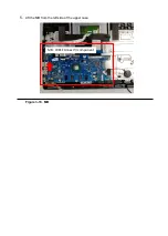
Disconnect the battery cable from the MB as shown in picture. 


Figure 3-8. Battery


4.


Remove the battery from the MB as shown in picture. 


Figure 3-9. Battery


Battery : WEEE Annex VII component


Содержание TravelMate B3

Страница 1: ...1 TravelMate B3 TM311R 31 TM311RN 31 TMB311 31 TMB311R 31 TMB311RN 31 TravelMate B311 31 TravelMate B311R 31 TravelMate B311RN 31 Lifecycle Extension Guide...

Страница 2: ...the Lower case 7 Removing the Battery 9 Removing the SSD 11 Removing the WLAN module 12 Removing the USB board 14 Removing the RJ45 board 15 Removing the MB 16 Removing theTouchpad module 19 Removing...

Страница 3: ...f repair NOTE Do not attempt to replace other components than those listed above NOTE For replacement parts always use only Acer certified components in order to safeguard quality optimum system perfo...

Страница 4: ...tart button go to Settings Update Security Windows Update Available Drivers will automatically be listed on screen Press Download to start the download of the respective driver Installation of the dri...

Страница 5: ...ted metal surface at the same time as touching a connector on the back of the computer Take off any metal objects on your arms or fingers such as bracelets rings or watches and make sure your hands ar...

Страница 6: ...h the disassembly procedure make sure to do the following 1 Turn off the power to the system and all peripherals 2 Unplug the AC adapter and all power and signal cables from the system 3 Place the sys...

Страница 7: ...he spec of NO 1 to NO 2 is SCREW_M2 5 6 7 mm_0 8 mm_4 mm_BLACK the spec of NO 3 to NO 13 is SCREW_M2 5 mm_0 8 mm_4 mm_BLACK Figure 3 3 Lower case Table 3 2 Lower case Screw Step Screw Quantity Screw T...

Страница 8: ...2 Open the buckle with a pick as showed figure3 4 then remove the lower case from the bottom side as shown in picture Figure 3 4 Lower case Figure 3 5 Lower case...

Страница 9: ...ews from upper case Figure 3 6 Battery Table 3 3 Battery Screw Step Screw Quantity Screw Type Torque kgfcm Remove battery SCREW_M2 4 mm_0 6 mm_5 mm_silver 2 1 8 0 1 kgf cm 2 Remove the acetate cloth f...

Страница 10: ...3 Disconnect the battery cable from the MB as shown in picture Figure 3 8 Battery 4 Remove the battery from the MB as shown in picture Figure 3 9 Battery Battery WEEE Annex VII component...

Страница 11: ...screw from SSD Figure 3 10 SSD Table 3 4 SSD Screw Step Screw Quantity Screw Type Torque kgfcm Remove SSD SCREW_M2 3mm_0 65 mm_5mm_BLACK_BLA CK 1 1 5 0 1 kgf cm 2 Remove SSD from MB Figure 3 11 SSD S...

Страница 12: ...ng the WLAN module 1 Remove the acetate cloth on the WLAN cable Figure 3 12 WLAN module 2 Disconnect the WLAN cable connectors on the WLAN module Please notice the color and position Figure 3 12 WLAN...

Страница 13: ...ure 3 13 WLAN module Table 3 5 WLAN Screw Step Screw Quantity Screw Type Torque kgfcm Remove WLAN SCREW_M2 3 mm_0 65 mm_5 mm_BLACK 1 1 5 0 1 kgf cm 4 Remove the WLAN module from the MB Figure 3 14 WLA...

Страница 14: ...oard Figure 3 19 USB board Table 3 7 USB board screw Step Screw Quantity Screw Type Torque kgfcm Remove USB board SCREW_M2 3 mm_0 65 mm_5 mm_BLACK 1 1 5 0 1 kgf cm 2 Remove the IO FFC from the USB boa...

Страница 15: ...igure 3 21 RJ45 board Table 3 8 RJ45 board screw Step Screw Quantity Screw Type Torque kgfcm Remove RJ45 board SCREW_M2 3mm_0 6 5 mm_5 mm_BLACK 2 1 5 0 1 kgf cm 2 Remove the FFC from the RJ45 board Fi...

Страница 16: ...ving the MB 1 Remove the acetate cloth from the KB FFC connector Figure 3 29 MB 2 Disconnect the FP FFC KB FFC LCD cable LVDS cable Glass version from the MB All of them are ZIF connectors Figure 3 30...

Страница 17: ...uppercase Figure 3 31 MB 4 Remove 6 screws on the MB Figure 3 32 MB Table 3 10 MB Screw Step Screw Quantity Screw Type Torque kgfcm Remove MB SCREW_M2 3mm_0 65 mm_5 mm_BLACK 7 1 5 0 1 kgf cm 1 2 3 5 4...

Страница 18: ...5 Lift the MB from the left side of the upper case Figure 3 33 MB MB WEEE Annex VII component...

Страница 19: ...hpad module 1 Disconnect the TP FFC connector on the touch pad then remove it from the touch pad Figure 3 34 Touch pad module 2 Remove the conductive cloth from the touchpad and upper case Figure 3 35...

Страница 20: ...w Step Screw Quantity Screw Type Torque kgfcm Remove Touch pad SCREW_M2 3mm_0 65 mm_5 mm_BLACK 1 1 8 0 1 kgf cm SCREW_M2 0 L3 0_T 0 65_D6 5 3 65mm_0 65 mm_6 5 mm_silver 3 1 8 0 1 kgf cm 4 Lift the bot...

Страница 21: ...Removing the LCD panel 1 Open the bezel from the left or right as below then remove the bezel from the LCD cover Bezel version Glass version Figure 3 45 LCD bezel...

Страница 22: ...ble Bezel version Figure 3 46 LCD panel 3 Pull the easy pull glue out of the LCD During the pulling it is necessary to apply even force and smoothness and the force is not too strong until the glue is...

Страница 23: ...module and LED module Figure 3 48 LCD panel 5 Pick up the LCD cable from the LCD cover groove flip the LCD panel from the top then remove the LCD from the LCD cover Figure 3 49 LCD panel Bezel version...

Страница 24: ...Figure 3 50 LCD panel Bezel version Glass version...

Страница 25: ...6 Disconnect the LCD cable from the LCD Figure 3 51 LCD panel...

Страница 26: ...Troubleshooting...

Страница 27: ...FRU Field Replaceable Unit List Please contact your local service center to find out how to obtain the part or replace your device...

Страница 28: ...ption Acer Part 1 BEZEL 60 VMUN8 002 7 LCD PANEL KL 1160D 019 2 SCREW 86 VMUN8 001 8 ANTENNA 50 VMUN8 004 3 LCD CABLE 50 VMUN8 005 9 EASY PULL GLUE 47 VMUN8 001 4 MIC RUBBER 47 VMUN8 002 10 CONDUCTIVE...

Страница 29: ...001 8 ANTENA 50 VMUN8 004 2 BEZEL 60 VMUN8 002 9 SCREW 86 VMUN8 001 3 LCD CABLE 50 VMYN8 002 10 CONDUCTIVE FOAM 47 VMUN8 003 4 MIC RUBBER 47 VMYN8 002 11 HINGE 33 VMYN8 001 5 CAMERA KS 0HD06 012 12 L...

Страница 30: ...001 4 RTC BATTERY Included in the MB 16 BATTERY KT 00304 012 5 WLAN MODULE KE 11A0N 010 17 RJ45 BOARD 55 VMUN8 002 6 SPEAKER 23 VMUN8 001 18 PEN CABLE 50 VMYN8 001 7 CAMERA KS 0HD06 012 19 UB FFC 50 V...

Страница 31: ...your PC to get to the sign in screen then press and hold down the Shift key while you select the Power icon Restart in the lower right corner of the screen After your computer restarts select Troubles...

Отзывы: