


Troubleshooting
4-2
Troubleshooting
This chapter contains information about troubleshooting common problems associated with the
tablet.
General Information
The following procedures are a guide for troubleshooting computer problems. The step by step
procedures are designed to be performed as described.
NOTE:
•
The diagnostic tests are intended to test only Acer products. Non-Acer products, prototype
cards, or modified options can give false errors and invalid system responses.
•
Do not replace a non-defective FRU.
1.
Obtain as much detail as possible about the problem.
2.
If possible, verify the symptoms by re-creating the failure through diagnostic tests or by
repeating the operation that led to the problem.
3.
Use Table 4-1 with the verified symptom(s) to determine the solution.
4.
If the issue is still not resolved, see
Online Support Information
on page
8-2
.
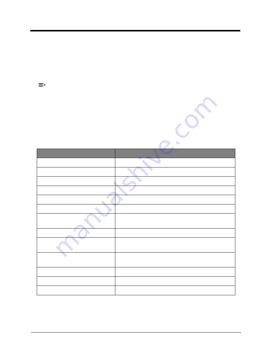
Table 4:1. Verified Symptoms
Symptoms
See
Power on Issues
Figure 4:1. Power On Issues
on page
4-3
No Display Issues
Figure 4:2. No Display Issues
on page
4-4
LCD Picture Failure
Figure 4:3. LCD Picture Failure
on page
4-6
Internal Keyboard Failure
Figure 4:4. Internal Keyboard Failure
on page
4-7
Touchpad Failure
Figure 4:5. Touchpad Failure
on page
4-8
Internal Speaker Failure
Figure 4:6. Internal Speaker Failure
on page
4-9
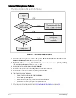
Internal Microphone Failure
Figure 4:7. Internal Microphone Failure
on page
4-
11
USB Failure
Figure 4:8. USB Failure
on page
4-12
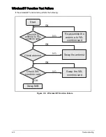
Wireless Function Failure
Figure 4:9. Wireless/BT Function Failure
on page
4-
13
2-in-1 Card Function Failure
Figure 4:10. 2-in-1 Card Function Failure
on page
4-
14
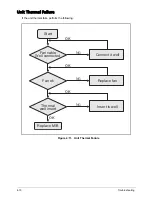
Units Thermal Failure
Figure 4:11. Unit Thermal Failure
on page
4-15
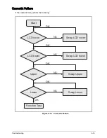
Cosmetic Failure
Figure 4:12. Cosmetic Failure
on page
4-16
Other Functions Failure
Page
4-17
Содержание TravelMate B113-M
Страница 1: ...TravelMate B113 Series S E R V I C E G U I D E G U I D E...
Страница 110: ...Service and Maintenance 5 14 Table 5 8 Base Door Screw Screw Name Screw Type Quantity M 2 0 x 6 0 1...
Страница 118: ...Service and Maintenance 5 22 4 Lift the fan by the fan cable to remove from its bay Figure 5 25 Removing the Fan...
Страница 140: ...Service and Maintenance 5 44 4 Lift to remove the IO board from the lower case Figure 5 58 Removing the IO Board...
Страница 148: ...Service and Maintenance 5 52 3 Lift to remove the left speaker Figure 5 70 Removing the Speakers 2 of 2...
Страница 152: ...Service and Maintenance 5 56 3 Lift to remove the keyboard Figure 5 76 Removing the Keyboard...
Страница 161: ...5 65 Service and Maintenance Table 5 18 Thermal Module Screws Screw Name Screw Type Quantity M 2 0 x 3 0 4...
Страница 164: ...Service and Maintenance 5 68 5 Lift to remove the LCD module from the lower case Figure 5 94 Removing the LCD Module...
Страница 171: ...5 75 Service and Maintenance 3 Lift to remove the LCD bezel Figure 5 104 Removing the LCD Bezel 3 of 3...
Страница 189: ...5 93 Service and Maintenance 3 Remove the main antenna from the LCD cover Figure 5 138 Removing the Main Antenna 3 of 3...
Страница 199: ...FRU Field Replaceable Unit List 6 6 Upper Case Assembly Figure 6 3 Upper Case Assembly Exploded Diagram 1 2 3 4 5...
Страница 201: ...FRU Field Replaceable Unit List 6 8 LCD Assembly Figure 6 4 LCD Assembly Exploded Diagram 1 2 3 4 5 8 9 6 7...
Страница 210: ...CHAPTER 7 Test Compatible Components Test Compatible Components 7 2 Microsoft Windows 7 Environment Test 7 2...
Страница 215: ...CHAPTER 8 Online Support Information Online Support Information 8 2 Introduction 8 2...
Страница 217: ......


