Acer TravelMate 8331 Series Скачать руководство пользователя страница 65

Chapter 4

57

Use the following procedure as a guide for computer problems.

NOTE: 

The diagnostic tests are intended to test only Acer products. Non-Acer products, prototype cards, or 

modified options can give false errors and invalid system responses.

1.

Obtain the failing symptoms in as much detail as possible.

2.

Verify the symptoms by attempting to re-create the failure by running the diagnostic test or by repeating 
the same operation.

3.

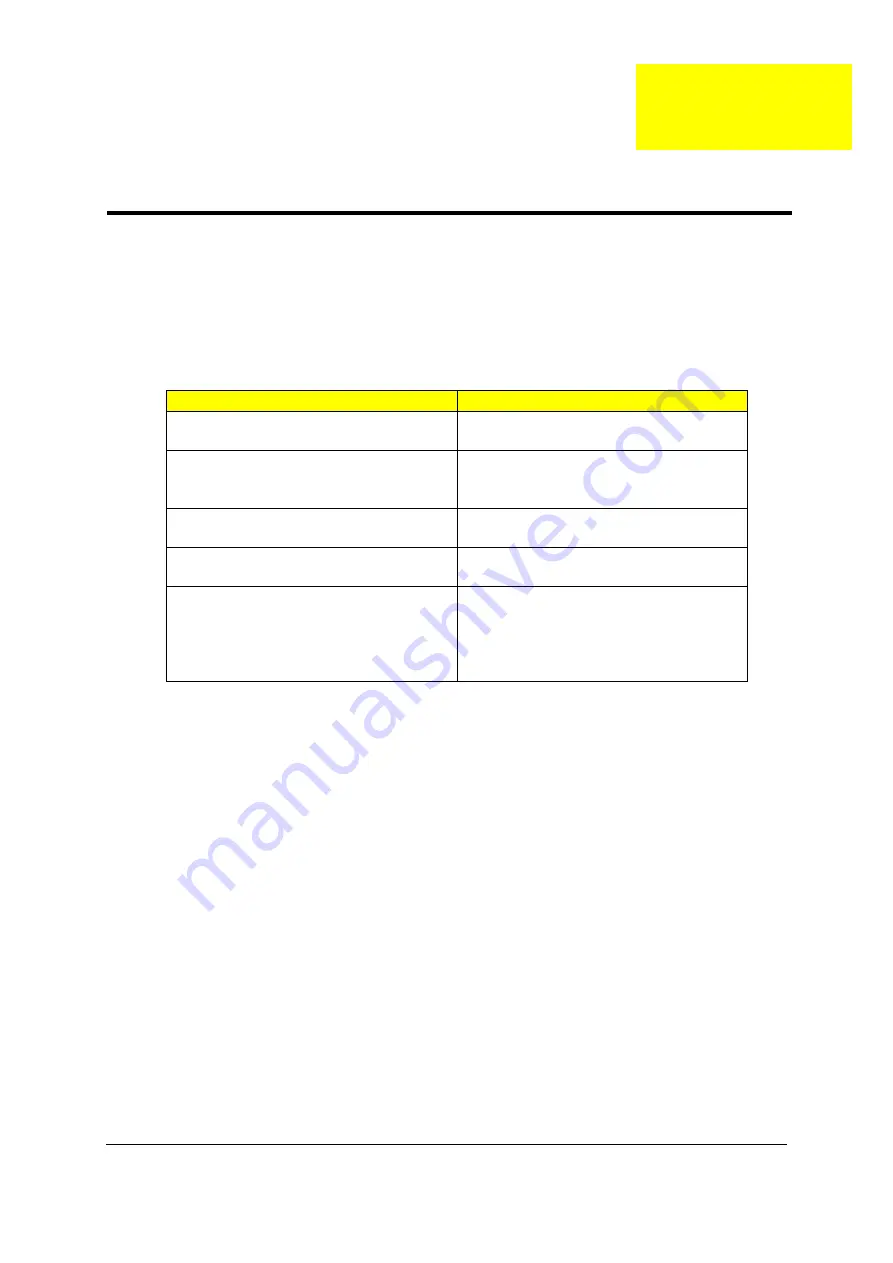
Use the following table with the verified symptom to determine which page to go to.

Symptoms (Verified)

Go To

Power failure. (The power indicator does not 
go on or stay on.)

“Power System Check” on page 59.

POST does not complete. No beep or error 
codes are indicated.

“Power-On Self-Test (POST) Error Message” 
on page 61.

“Undetermined Problems” on page 74.

POST detects an error and displayed 
messages on screen.

“Error Message List” on page 62.

Other symptoms (i.e. LCD display problems or 
others).

“Power-On Self-Test (POST) Error Message” 
on page 61.

Symptoms cannot be re-created (intermittent 
problems).

Use the customer-reported symptoms and go 
to “Power-On Self-Test (POST) Error 
Message” on page 61.

“Intermittent Problems” on page 73.

“Undetermined Problems” on page 74.

Troubleshooting

Chapter 4

Содержание TravelMate 8331 Series

Страница 1: ...TravelMate 8371 8331 Series Service Guide PRINTED IN TAIWAN Service guide files and updates are available on the ACER CSD web for more information please refer to http csd acer com tw ...

Страница 2: ...II Revision History Please refer to the table below for the updates made on TravelMate 8371 8331 service guide Date Chapter Updates ...

Страница 3: ...pect to the contents hereof and specifically disclaims any warranties of merchantability or fitness for any particular purpose Any Acer Incorporated software described in this manual is sold or licensed as is Should the programs prove defective following their purchase the buyer and not Acer Incorporated its distributor or its dealer assumes the entire cost of all necessary servicing repair and an...

Страница 4: ... bits and pieces of additional information related to the current topic WARNING Alerts you to any damage that might result from doing or not doing specific actions CAUTION Gives precautionary measures to avoid possible hardware or software problems IMPORTANT Reminds you to do specific actions relevant to the accomplishment of procedures ...

Страница 5: ... NOT be covered in this generic service guide In such cases please contact your regional offices or the responsible personnel channel to provide you with further technical details 2 Please note WHEN ORDERING FRU PARTS that you should check the most up to date information available on your regional web or channel If for whatever reason a part number change is made it will not be noted in the printe...

Страница 6: ...VI ...

Страница 7: ...s 15 Hot Keys 16 Special Key 16 Using the system utilities 18 Acer Backup Manager 20 Power management 21 Acer PowerSmart key 21 Acer eRecovery Management 21 Burn backup discs 22 Restore 23 Acer Arcade Deluxe 24 General controls 25 Navigation controls 25 Player controls 25 Cinema 25 HomeMedia 26 Advanced 26 Albums 27 Editing Pictures 27 Slideshow settings 27 Music 27 Online Media 28 YouTube 28 Flic...

Страница 8: ...Troubleshooting 57 System Check Procedures 58 External Diskette Drive Check 58 External CD ROM Drive Check 58 Keyboard or Auxiliary Input Device Check 58 Memory check 59 Power System Check 59 Touchpad Check 60 Power On Self Test POST Error Message 61 Index of Error Messages 62 InsydeH2O BIOS Beep Codes 65 Index of Symptom to FRU Error Message 69 Intermittent Problems 73 Undetermined Problems 74 To...

Страница 9: ...ss Chipset Intel Wireless WiFi Link 5100 Acer InviLink Nplify 802 11b g Draft N Acer InviLink 802 11b g System memory Dual Channel SDRAM support Up to 2 GB of DDR3 1066 MHz memory upgradeable to 4 GB using two soDIMM modules Up to 4 GB of DDR3 1066 MHz memory upgradeable to 8 GB using two soDIMM modules Display 16 9 aspect ratio 13 3 HD 1366 x 768 Graphics Mobile Intel GS45 Express Chipset ATI Mob...

Страница 10: ...ction Acer Bio Protection fingerprint solution BIOS user supervisor HDD passwords Kensington lock slot Dimensions and weight 323 6 W x 228 D x 26 29 4 H mm 12 74 x 8 97 x 1 02 1 10 inches 1 65 kg 3 583 lbs with 6 cell battery pack Power subsystem ACPI 3 0 62 16 W 5600 mAh 3 pin 65 W AC adapter ENERGY STAR Special keys and controls 88 89 93 key keyboard Touchpad pointing device I O Ports Acer EasyP...

Страница 11: ...o 35 C z Non operating 20 C to 65 C Humidity non condensing z operating 20 80 z Non operating 20 80 NOTE only for certain models NOTE The specifications listed above are for reference only The exact configuration of your PC depends on the model purchased ...

Страница 12: ...Express x1 2 5GHz Port 4 PCI Express x1 2 5GHz Port 1 RJ45 P 37 Port 1 MiniCard 1 WLAN Codec ALC269X GR P 39 Out Out IN IN ITE8502F P 45 Flash ROM DDR3 1 5V 800 1066MHz DDR3 1 5V 800 1066MHz FSB 1 05V 667 800 1066MHz TSSP 64P IN P 37 P 37 USB2 P 43 USB4 Port 3G USB3 USB6 P 43 USB8 WLAN USB9 BlueTooth USB11 PCI Express x1 2 5GHz Port 2 PCI Express x1 2 5GHz Port 6 Stick USB10 22mmx22mm REALTEK RTS5...

Страница 13: ...d connector location TOP view No Name Description 1 CN1 CCD cable CNTR 2 CN2 MMB cable CNTR 3 CN3 LVDS cable CNTR 4 CN4 Keyboard CNTR 5 CN5 Touch Pad FFC CNTR 6 CN6 SSD cable CNTR 7 CN7 Card reader CNTR 8 CN8 BT cable CNTR 9 CN15 Fan cable CNTR 10 CN21 Audio board CNTR ...

Страница 14: ... 11 CN9 Battery CNTR 12 CN10 PCI E socket 13 CN11 SIM card socket 14 CN12 PCI E socket 15 CN13 Power cable CNTR 16 CN14 LVDS cable CNTR 17 CN16 DIMM socket 18 CN17 DIMM socket 19 CN19 HDD socket 20 CN20 USB board CNTR 21 U18 South Bridge 22 U14 North Bridge ...

Страница 15: ...al Eye webcam Web camera for video communication 2 Microphone Internal microphone for sound recording 3 Display screen Also called Liquid Crystal Display LCD displays computer output Configuration may vary by models 4 Speakers Left and right speakers deliver stereo audio output 5 Keyboard For entering data into your computer 6 Touchpad Touch sensitive pointing device which functions like a compute...

Страница 16: ...es when the hard disk drive is active Num Lock Lights up when Num Lock is activated Caps Lock Lights up when Caps Lock is activated 11 Communication key Enables disables the WLAN 3G functions Backup key Launches Acer Backup Management for three step data backup Acer PowerSmart key Puts your computer into power saving mode 12 Power button indicator Turns the computer on and off Indicates the comput...

Страница 17: ...a locked drawer Insert the lock into the notch and turn the key to secure the lock Some keyless models are also available 2 External display VGA port Connects to a display device e g external monitor LCD projector 3 Ventilation slots Enable the computer to stay cool even after prolonged use 4 USB 2 0 ports Connect to USB 2 0 devices e g USB mouse USB camera 5 Microphone in jack Accepts inputs from...

Страница 18: ...RO MS PRO xD Picture Card xD NOTE Push to remove install the card Only one card can operate at any given time 2 USB 2 0 port Connects to USB 2 0 devices e g USB mouse USB camera 3 Ethernet RJ 45 port Connects to an Ethernet 10 100 1000 based network 4 Acer EasyPort IV connector Connects to Acer EasyPort IV 5 DC in jack Connects to an AC adapter ...

Страница 19: ...position 3 Memory compartment Houses the computer s main memory 4 Hard disk bay Houses the computer s hard disk secured with screws 5 Ventilation slots and cooling fan Enable the computer to stay cool even after prolonged use NOTE Do not cover or obstruct the opening of the fan 6 Battery release latch Releases the battery for removal ...

Страница 20: ...chpad basics with two click buttons The following items show you how to use the touchpad with two click buttons Move your finger across the touchpad to move the cursor Press the left and right buttons located beneath the touchpad to perform selection and execution functions These two buttons are similar to the left and right buttons on a mouse Tapping on the touchpad is the same as clicking the le...

Страница 21: ...s NOTE By default vertical and horizontal scrolling is enabled on your touchpad It can be disabled under Mouse settings in Windows Control Panel Function Left Button Right Button Main touchpad Execute Quickly click twice Tap twice at the same speed as double clicking a mouse button Select Click once Tap once Drag Click and hold then use finger on the touchpad to drag the cursor Tap twice at the sa...

Страница 22: ...um Lock Fn F11 When Num Lock is on the embedded keypad is in numeric mode The keys function as a calculator complete with the arithmetic operators and Use this mode when you need to do a lot of numeric data entry A better solution would be to connect an external keypad Scroll Lock Fn F12 When Scroll Lock is on the screen moves one line up or down when you press the up or down arrow keys respective...

Страница 23: ...rk domain M Minimizes all windows R Open the Run dialog box T Cycle through programs on the taskbar U Open Ease of Access Center X Open Windows Mobility Center BREAK Display the System Properties dialog box SHIFT M Restore minimized windows to the desktop TAB Cycle through programs on the taskbar by using Windows Flip 3 D SPACEBAR Bring all gadgets to the front and select Windows Sidebar CTRL F Se...

Страница 24: ...Starts System Property for displaying system information Fn F3 Bluetooth Enables disables the Bluetooth function only for certain models Fn F4 Sleep Puts the computer in Sleep mode Fn F5 Display toggle Switches display output between the display screen external monitor if connected and both Fn F6 Screen blank Turns the display screen backlight off to save power Press any key to return Fn F8 Speake...

Страница 25: ...keyboard NOTE Some fonts and software do not support the Euro symbol Please refer to www microsoft com typography faq faq12 htm for more information The US dollar sign 1 Open a text editor or word processor 2 Hold Shift and then press the 4 key at the upper center of the keyboard NOTE This function varies by the operating system version ...

Страница 26: ...r FingerLaunch Acer ProfileLaunch can launch up to three applications websites with a single finger swipe Acer Bio Protection Fingerprint Solution also allows you to navigate through web browsers and documents using Acer FingerNav With Acer Bio Protection Fingerprint Solution you can now enjoy an extra layer of protection for your personal computer as well as the convenience of accessing your dail...

Страница 27: ...m the new settings and click OK to complete the process Acer GridVista is a handy utility that offers four pre defined display settings so you can view multiple windows on the same screen To access this function please go to Start All Programs and click on Acer GridVista You may choose any one of the four display settings indicated below Double vertical Triple primary at left Triple primary at rig...

Страница 28: ...ou will be taken through the three steps to setup scheduled back ups Click Continue to proceed to the following screen Click the button and follow the onscreen instructions 1 Select the content you want to back up The less content you select the quicker the process will be but it will increase your risks of losing data 2 Select where you want the backup copies to be stored You will need to select ...

Страница 29: ...witch to power saving modes Press the Acer PowerSmart key again to return to your previous settings NOTE This feature is only available on certain models Acer eRecovery Management Acer eRecovery Management is a tool to quickly restore the system You can back up restore the factory default image and reinstall applications and drivers NOTE All of the following content is for general reference only A...

Страница 30: ...actory default or drivers and applications you would like to burn to disc 4 Follow the instructions on screen to complete the process NOTE Create a factory default image when you want to burn a bootable disc that contains your computer s entire operating system as it was delivered to you from the factory If you wish to have a disc that will allow you to browse the contents and install selected dri...

Страница 31: ... Setup where you can set system parameters 3 Use the left and right arrow keys to select the Main submenu 4 Use the up and down arrow keys to select F12 Boot Menu 5 Use the F5 or F6 key to change F12 Boot Menu to Enabled 6 Press the ESC key to enter the Exit submenu press the ENTER key to Exit Saving Changes Press the ENTER key again to select Yes The system will reboot 7 After rebooting when the ...

Страница 32: ...e the recovery disc from the optical drive once the restore is complete Do this before rebooting your computer Acer Arcade Deluxe Acer Arcade Deluxe is an integrated player for music photos DVD movies and videos Use the MediaConsole touchpad or arrow keys to select the media type you wish to enjoy Cinema watch DVDs VCDs or Blu Ray movies and video clips Homemedia connect to other devices wirelessl...

Страница 33: ...Deluxe This player has the features and controls of a typical DVD player When you insert a disk into the DVD drive the movie begins playing automatically To control the movie the pop up player control panel appears at the bottom of the window when you move the pointer If more than one optical drive contains a playable disc you will be asked to select which one you would like to watch when you clic...

Страница 34: ...ne and your personal preferences Live Update Click Live Update to connect to the Internet to check for and download available updates to the software Settings Click Settings to make various adjustments to your Acer Arcade Deluxe Here you will be able to modify Display Audio Photo DVD and BD settings to get the best out of your computer Display Use this section to set the display type You can choos...

Страница 35: ...at shows both individual pictures and folders Click on a folder to open it To view a slideshow open the folder containing the pictures you wish to view select all or some of the pictures and click Slideshow The slideshow is played at fullscreen resolution Use the pop up control panel to control the slideshow You can also view a single picture by clicking on it This opens the picture at fullscreen ...

Страница 36: ... be displayed as thumbnails select a thumbnail to view the video clip s title and number of views Press Enter or double click a thumbnail to view the video Alternatively you can log into your YouTube account to view your favorite video clips You need to be logged in to save a video clip to your favorites Flickr Select Flickr to view 200 recently uploaded photos on Flickr You can log into your Flic...

Страница 37: ...e BGA Item Specification North Bridge GS45 South Bridge ICH9M SFF Item Specification Technology DDR3 800 1067 MHz Base momory DDR3 SO DIMM x 1 slot 512 1024 2048 4096MB DDR3 SDRAM Expansion memory DDR3 SO DIMM x 1 slot 512 1024 2048 4096MB DDR3 SDRAM Maximum memory size 8 GB Thermal evaluation based on 8 GB Item Specification Controller AVAP Atheros AR8131 SPEED 10 100 1000Mb s Item Specification ...

Страница 38: ...ia I F SATA IDE Controller SATA 150 MB s SSD Media size 80 GB Option SATA I F SSD form factor 2 5 factor Item Specification Sound Codec AVAP Realtek ALC269 Internal Speaker 2 1 5 Watt Internal Microphone Array MIC x 1 Sound Volume By Hot Key Item Specification Panel size 13 3 13 4 WXGA HD 720p 1366 x 768 LVDS Embedded in Cantigata GM Brightness Brightness controlled by Hot Keys Item Specification ...

Страница 39: ... Half mini card SP WLAN x 1 Item Specification Power on off with Visiable LED 1 mechanical White WLAN 1 Orange capacitive 3G BT BT Blue capacitive 3G use SW to launch without button Launch Key module None Back up Key 1 capacitive Blue flash Power consumption key 1 mechanical Green Volume Control Volume up down mute capacitive blue Item Specification Operation system Vista BIOS InsydeH2O Item Speci...

Страница 40: ...m Lock 1 Blue Wireless LAN 1 Orange Bluetooth 1 Blue Touch pad on off 1 capacitive Orange top side 3G 1 Green Item Specification Kensington Lock Hole 7 5 mm diameter 1 Item Specification Not Nosie as low as possible Number 1 Item Specification Dimensions 323 6 W x 228 D x 26 29 4 H mm Thickness maximum 23 3 28 9mm Weight incl 1st Battery super multi ODD 1 65 kg 3 583 lbs with 6 cell battery pack ...

Страница 41: ...lease also refer to Chapter 4 Troubleshooting when problem arises To activate the BIOS Utility press m during POST when Press F2 to enter Setup message is prompted on the bottom of screen Press m to enter setup The default parameter of F12 Boot Menu is set to disabled If you want to change boot device without entering BIOS Setup Utility please set the parameter to enabled Press F12 during POST to ...

Страница 42: ...ting and exit Setup NOTE You can change the value of a parameter if it is enclosed in square brackets Navigation keys for a particular menu are shown on the bottom of the screen Help for parameters are found in the Item Specific Help part of the screen Read this carefully when making changes to parameter values Please note that system information is subject to different models Information NOTE The...

Страница 43: ...ally detected by the system HDD1 Serial Number The field shows the serial number of devices installed on secondary master System BIOS version Displays system BIOS version VGA BIOS Version This field displays the VGA firmware version of the system Serial Number This field displays the serial number of this unit Asset Tag Number This field displays the asset tag number of the system Product Name Thi...

Страница 44: ...ry in the system Video Memor Shows the Video memory size Quiet Boot Determines if Customer Logo will be displayed or not shows Summary Screen is disabled or enabled Enabled Customer Logo is displayed and Summary Screen is disabled Disabled Customer Logo is not displayed and Summary Screen is enabled Option Enabled or Disabled Network Boot Enables disables the system boot from LAN remote server Opt...

Страница 45: ...Chapter 2 37 Security The Security screen contains parameters that help safeguard and protect your computer from unauthorized use ...

Страница 46: ...ord parameter to Set Parameter Description Option Supervisor Password is Shows the setting of the Supervisor password Clear or Set User Password is Shows the setting of the user password Clear or Set HDD Password is Shows the setting of HDD password Clear or Set Set Supervisor Password Press Enter to set the supervisor password When set this password protects the BIOS Setup Utility from unauthoriz...

Страница 47: ...hen you have changed the settings press u to save the changes and exit the BIOS Setup Utility Changing a Password 1 Use the w and y keys to highlight the Set Supervisor Password parameter and press the e key The Set Password box appears 2 Type the current password in the Enter Current Password field and press e 3 Type a password in the Enter New Password field Retype the password in the Confirm Ne...

Страница 48: ...ning If the new password and confirm new password strings do not match the screen will display the following message Boot This menu allows the user to decide the order of boot devices to load the operating system Bootable devices includes the distette drive in module bay the onboard hard disk drive and the CD ROM in module bay ...

Страница 49: ...he parameters in this screen Parameter Description Exit Saving Changes Exit System Setup and save your changes to CMOS Exit Discarding Changes Exit utility without saving setup data to CMOS Load Setup Default Load default values for all SETUP item Discard Changes Load previous values from CMOS for all SETUP items Save Changes Save Setup Data to CMOS ...

Страница 50: ... Diskette before you use the Phlash utility NOTE Do not install memory related drivers XMS EMS DPMI when you use the Phlash NOTE Please use the AC adaptor power supply when you run the Phlash utility If the battery pack does not contain enough power to finish BIOS flash you may not boot the system because the BIOS is not completely loaded Fellow the steps below to run the Phlash 1 Prepare a bootab...

Страница 51: ...uctive mat for preventing electrostatic discharge Small Philips screw driver Philips screwdriver Plastic flat head screw driver Tweezers NOTE The screws for the different components vary in size During the disassembly process group the screws with the corresponding components to avoid mismatch when putting back the components When you remove the stripe cover please be careful not to scrape the cov...

Страница 52: ... Begin Before proceeding with the disassembly procedure make sure that you do the following 1 Turn off the power to the system and all peripherals 2 Unplug the AC adapter and all power and signal cables from the system 3 Remove the battery pack ...

Страница 53: ...components that need to be removed during servicing For example if you want to remove the system board you must first remove the keyboard then disassemble the inside assembly frame in that order Main unit disassembly flow chart LCM module disassembly flow chart Start RAM HDD Battery BTCB Audio Board VGA Board LCM Module I O Board Main Board Start LCM Mylar LCM Bezel LCM Panel ...

Страница 54: ...ery Pack 1 Release the battery lock 2 Slide the battery latch then remove the battery NOTE Battery has been highlighted with the yellow circle as above image shows Please detach the battery and follow local regulations for disposal ...

Страница 55: ...Chapter 3 47 Removing the HDD and RAM 3 Remove two screws on the HDD cover and remove HDD Type Number M2 5 4 5D 0 8T 2 ...

Страница 56: ... and remove both of RAM Remove the Battery 5 Remove RTC battery NOTE RTC battery has been highlighted with the yellow circle as above image shows Please detach the RTC battery and follow local regulations for disposal Type Number M2 5 4 5D 0 8T 1 ...

Страница 57: ...move the rubber and remove all of the screws on the back of the notebook Remove keyboard 7 Disconnect five latches on the keyboard 8 Remove the FFC behind the keyboard Type Number M2 5 4 5D 0 8T 13 Red Type Number M2 5 4 5D 0 5T 2 Yellow ...

Страница 58: ...apter 3 Remove FFC of main board and sub board 9 Remove screws and FFC on the upper case 10 Remove the upper case and disconnect the connector between upper case and audio board Type Number M2 5 4 5D 0 8T 8 ...

Страница 59: ...Chapter 3 51 11 Remove Audio board 12 Remove the FFC and screw on the audio board 13 Remove audio board ...

Страница 60: ...apter 3 14 Remove the connector of I O board and then release a screw on the I O board 15 Remove I O board after removing the connector under I O board 16 Remove Bluetooth board Type Number M2 5 4 5D 0 8T 1 ...

Страница 61: ...Chapter 3 53 17 Remove two screws on the VGA board 18 Remove VGA board 19 Remove the LAN connection and two screws and remove wireless card Type Number M2 5 4 5D 0 8T 2 Type Number M2 5 3 4 5D 0 8T 2 ...

Страница 62: ...54 Chapter 3 20 Remove all of the connectors on the main board 21 Remove the screw on the fan module and three screws on the thermal module Type Number M2 5 4 5D 0 8T 2 Type Number M2 3 4 5D 0 8T 4 ...

Страница 63: ... Remove Panel 22 Remove eight screws on the bottom of panel and remove the panel 23 Remove six sponges on the LCD and remove 6 screws under them Type Number M2 4 4 5D 0 5T 4 Red Type Number M2 3 4 5D 0 8T 2 Yellow ...

Страница 64: ...e bezel on the panel and remove four screws on it 25 Remove LCM cable on the back of panel Disassembling the External Module Disassembling the HDD Module 1 Remove HDD bezel and get HDD out of cover Type Number M2 2 4 5D 0 5T 4 ...

Страница 65: ... which page to go to Symptoms Verified Go To Power failure The power indicator does not go on or stay on Power System Check on page 59 POST does not complete No beep or error codes are indicated Power On Self Test POST Error Message on page 61 Undetermined Problems on page 74 POST detects an error and displayed messages on screen Error Message List on page 62 Other symptoms i e LCD display problem...

Страница 66: ...e the drive to fail Do the following to select the test device 1 Boot from the diagnostics diskette and start the diagnostics program 2 See if CD ROM Test is passed when the program runs to CD ROM Test 3 Follow the instructions in the message window If an error occurs reconnect the connector on the System board If the error still remains 1 Reconnect the external diskette drive CD ROM module 2 Repl...

Страница 67: ...k the Power Adapter Unplug the power adapter cable from the computer and measure the output voltage at the plug of the power adapter cable See the following figure 1 If the voltage is not correct replace the power adapter 2 If the voltage is within the range do the following z Replace the System board z If the problem is not corrected see Undetermined Problems on page 74 z If the voltage is not co...

Страница 68: ...rature Re install the battery pack If the charge indicator still does not light up replace the battery pack If the charge indicator still does not light up replace the DC DC charger board Touchpad Check If the touchpad doesn t work do the following actions one at a time to correct the problem Do not replace a non defective FRU 1 Reconnect the touchpad cables 2 Replace the touchpad 3 Replace the sy...

Страница 69: ...ext possible FRU to be replaced when servicing a computer If the symptom is not listed see Undetermined Problems on page 74 The following lists the error messages that the BIOS displays on the screen and the error symptoms classified by function NOTE Most of the error messages occur during POST Some of them display information about a hardware device e g the amount of memory installed Others may i...

Страница 70: ...r code Thermal critical High In this situation BIOS will shut down system not show message Error Messages FRU Action in Sequence Failure Fixed Disk Reconnect hard disk drive connector Load Default Settings in BIOS Setup Utility Hard disk drive System board Stuck Key see Keyboard or Auxiliary Input Device Check on page 58 Keyboard error see Keyboard or Auxiliary Input Device Check on page 58 Keyboa...

Страница 71: ... size found by POST differed from CMOS Run Load Default Settings in BIOS Setup Utility DIMM System board Diskette drive A error Check the drive is defined with the proper diskette type in BIOS Setup Utility See External Diskette Drive Check on page 58 Incorrect Drive A type run SETUP Check the drive is defined with the proper diskette type in BIOS Setup Utility System cache error Cache disabled Sy...

Страница 72: ...cted tightly and correctly Reconnect the DIMM LED board System board No beep power on indicator turns on and LCD is blank Power source battery pack and power adapter See Power System Check on page 59 Reconnect the LCD connector Hard disk drive LCD inverter ID LCD cable LCD Inverter LCD System board No beep power on indicator turns on and LCD is blank But you can see POST on an external CRT Reconne...

Страница 73: ...itialize cache before memory autosize 18h 8254 timer initialization 1Ah 8237 DMA controller initialization 1Ch Reset Programmable Interrupt Controller 20h 1 3 1 1 Test DRAM refresh 22h 1 3 1 3 Test 8742 Keyboard Controller 24h Set ES segment register to 4 GB 26h Enable A20 line 28h Autosize DRAM 29h Initialize POST Memory Manager 2Ah Clear 215 KB base RAM 2Ch 1 3 4 1 RAM failure on address line xx...

Страница 74: ...he registers 67h Initialize Multi Processor APIC 68h Enable external and CPU caches 69h Setup System Management Mode SMM area 6Ah Display external L2 cache size 6Bh Load custom defaults optional 6Ch Display shadow area message 6Eh Display possible high address for UMB recovery 70h Display error messages 72h Check for configuration errors 76h Check for keyboard errors 7Ch Set up hardware interrupt ...

Страница 75: ...gine optional 9Eh Enable hardware interrupts 9Fh Determine number of ATA and SCSI drives A0h Set time of day A2h Check key lock A4h Initialize Typematic rate A8h Erase F2 prompt AAh Scan for F2 key stroke ACh Enter SETUP AEh Clear Boot flag B0h Check for errors B2h POST done prepare to boot operating system B4h 1 One short beep before boot B5h Terminate QuietBoot optional B6h Check password option...

Страница 76: ...E5h Check force recovery boot E6h Checksum BIOS ROM E7h Go to BIOS E8h Set Huge Segment E9h Initialize Multi Processor EAh Initialize OEM special code EBh Initialize PIC and DMA ECh Initialize Memory type EDh Initialize Memory size EEh Shadow Boot Block EFh System memory test F0h Initialize interrupt vectors F1h Initialize Run Time Clock F2h Initialize video F3h Initialize System Management Mode F...

Страница 77: ...or displayed Reconnect the LCD connector LCD inverter ID LCD cable LCD inverter LCD System board LCD has extra horizontal or vertical lines displayed LCD inverter ID LCD inverter LCD cable LCD System board Symptom Error Action in Sequence Indicator incorrectly remains off or on but system runs correctly Reconnect the inverter board Inverter board System board Symptom Error Action in Sequence Power...

Страница 78: ...ars different from actual size Enter BIOS Setup Utility to execute Load Default Settings then reboot system DIMM System board Symptom Error Action in Sequence In Windows multimedia programs no sound comes from the computer Audio driver Speaker System board Internal speakers make noise or emit no sound Speaker System board Symptom Error Action in Sequence The system will not enter hibernation Keybo...

Страница 79: ... the LCD LCD cover switch System board Battery fuel gauge in Windows doesn t go higher than 90 Remove battery pack and let it cool for 2 hours Refresh battery continue use battery until power off then charge battery Battery pack System board System hangs intermittently Reconnect hard disk CD ROM drives Hard disk connection board System board Symptom Error Action in Sequence ...

Страница 80: ...rk correctly System board Print problems Ensure the Parallel Port in the Onboard Devices Configuration of BIOS Setup Utility is set to Enabled Onboard Devices Configuration Run printer self test Printer driver Printer cable Printer System Board Serial or parallel port device problems Ensure the Serial Port in the Devices Configuration of BIOS Setup Utility is set to Enabled Device driver Device ca...

Страница 81: ... discharge or software errors FRU replacement should be considered only when a recurring problem exists When analyzing an intermittent problem do the following 1 Run the advanced diagnostic test for the system board in loop mode at least 10 times 2 If no error is detected do not replace any FRU 3 If any error is detected replace the FRU Rerun the test to verify that there are no more errors ...

Страница 82: ...operating correctly See Power System Check on page 59 1 Power off the computer 2 Visually check them for damage If any problems are found replace the FRU 3 Remove or disconnect all of the following devices z Non Acer devices z Printer mouse and other external devices z Battery pack z Hard disk drive z DIMM z CD ROM Diskette drive Module z PC Cards 4 Power on the computer 5 Determine if the problem...

Страница 83: ...iew No Name Description 1 CN1 CCD cable CNTR 2 CN2 MMB cable CNTR 3 CN3 LVDS cable CNTR 4 CN4 Keyboard CNTR 5 CN5 Touch Pad FFC CNTR 6 CN6 SSD cable CNTR 7 CN7 Card reader CNTR 8 CN8 BT cable CNTR 9 CN15 Fan cable CNTR 10 CN21 Audio board CNTR Jumper and Connector Locations Chapter 5 ...

Страница 84: ... 11 CN9 Battery CNTR 12 CN10 PCI E socket 13 CN11 SIM card socket 14 CN12 PCI E socket 15 CN13 Power cable CNTR 16 CN14 LVDS cable CNTR 17 CN16 DIMM socket 18 CN17 DIMM socket 19 CN19 HDD socket 20 CN20 USB board CNTR 21 U18 South Bridge 22 U14 North Bridge ...

Страница 85: ... is made it will not be noted on the printed Service Guide For ACER AUTHORIZED SERVICE PROVIDERS your Acer office may have a DIFFERENT part number code from those given in the FRU list of this printed Service Guide You MUST use the local FRU list provided by your regional Acer office to order FRU parts for repair and service of customer machines NOTE To scrap or to return the defective parts you s...

Страница 86: ...78 Chapter 6 TravelMate 8371 8331 Exploded Diagram ...

Страница 87: ...Chapter 6 79 ...

Страница 88: ...80 Chapter 6 ...

Страница 89: ...T 50 TTD0N 015 WIRELESS ANTENNA LEFT 3G 50 TTD0N 018 WIRELESS ANTENNA RIGHT 3G 50 TTD0N 019 Category Part Name and Description Acer Part No ADAPTER DELTA 65W 19V 1 7X5 5X11 YELLOW ADP 65MH B A LV5 LF LF AP 06501 027 ADAPTER LITE ON 65W 19V 1 7X5 5X11 YELLOW PA 1650 22AG LV5 LF AP 06503 026 ADAPTER HIPRO 65W 19V 1 7X5 5X11 YELLOW HP A0653R3B 1LF LV5 LF AP 0650A 013 ...

Страница 90: ... AS09D36 BT 00603 092 BATTERY SIMPLO AS 2009D LI ION 3S2P SAMSUNG 6 CELL 5600MAH MAIN COMMON ID AS09D70 W HALOGEN FREE BT 00607 082 BATTERY PANASONIC LI ION 3S2P PANASONIC 6 CELL 5800MAH MAIN COMMON W HALOGEN FREE BT 00605 038 BATTERY SANYO AS 2009D LI ION 3S2P SANYO 6 CELL 4400MAH MAIN COMMON ID AS09D31 W HALOGEN FREE BT 00603 082 BATTERY SONY AS 2009D LI ION 3S2P SONY 6 CELL 4400MAH MAIN COMMON ...

Страница 91: ...FOXCONN WIRELESS LAN ATHEROS HB93 1x2 BGN HM NI 23600 046 QUALCOMM 3G MODULE GOBI2000 LC 21300 011 HUAWEI 3G MODULE EM770W LC 21300 008 BLUETOOTH BOARD FOXCONN BRM 2046 BT2 1 T60H928 33 BH 21100 004 TOUCHPAD 56 PCR0N 001 I O BOARD 55 TTD0N 001 TOUCH PAD BUTTON BOARD W FP 55 TTD0N 002 TOUCH PAD BUTTON BOARD W O FP 55 TTD0N 003 HOTKEY BOARD 55 TTD0N 004 AUDIO BOARD 55 TTD0N 005 D SUB BOARD 55 TTD0N ...

Страница 92: ...3PIN UK 27 AAMVN 004 POWER CORD 3PIN SWISS 27 AAMVN 006 POWER CORD AUSTRALIA W LABEL 27 AAMVN 003 POWER CORD 3PIN CHINA 27 AAMVN 005 POWER CORD SOUTH AFRICA AIL 27 AAMVN 007 POWER CORD 3PIN TAIWAN 27 APQ0N 001 HOTKEY BOARD CABLE 8P 50 TTD0N 001 TOUCH PAD BUTTON BOARD CABLE 16P 50 TTD0N 002 TOUCH PAD CABLE 12P 50 TTD0N 003 IO BOARD CABLE 16P 50 TTD0N 004 IO BOARD CABLE 20P 50 TTD0N 005 AUDIO BOARD ...

Страница 93: ...RD CABLE 40P 50 TTD0N 012 IO BOARD CABLE 12P UMA 50 TTD0N 013 IO BOARD CABLE 12P DISCRETE 50 TTK0N 001 LED LCD CABLE UMA 50 TTD0N 016 LED LCD CABLE DISCRETE 50 TTK0N 002 CCD CABLE 50 TTD0N 017 Category Part Name and Description Acer Part No CCD 1 0M SUYIN CN1014 S36D OV05 R LAVENDER_G 57 PCR0N 001 Category Part Name and Description Acer Part No ...

Страница 94: ...ARD BRACKET 33 WEK0N 001 RAM COVER 60 TTD0N 001 HDD COVER 60 TTD0N 002 TOUCH PAD BRACKET 60 TTD0N 003 DUMMY CARD W LOGO 60 TTD0N 004 UPPER CASE W FP 60 TTD0N 005 UPPER CASE W O FP 60 TTD0N 006 LOWER CASE 60 TTD0N 007 HDD CONNECTOR 20 PCR0N 001 LCD HINGE LEFT 33 TTD0N 001 LCD HINGE RIGHT 33 TTD0N 002 ...

Страница 95: ...Chapter 6 87 LCD COVER 13 3 60 TTD0N 009 LCD BEZEL 13 3 W CCD HOLE 60 TTD0N 010 Category Part Name and Description Acer Part No ...

Страница 96: ...F W C60F KH 25007 015 HDD WD 2 5 5400RPM 250GB WD2500BEVT 22ZCT0 ML160 SATA LF F W 11 01A11 KH 25008 021 HDD 320GB 5400RPM SATA SEAGATE ST9320320AS LF F W 0303 KH 32001 008 HDD HGST 2 5 5400RPM 320GB HTS545032B9A300 PANTHER B SATA LF F W C60F KH 32004 002 HDD HGST 2 5 5400RPM 320GB HTS545032B9A300 PANTHER B SATA LF F W C60F KH 32007 007 HDD 320GB 5400RPM SATA WD WD3200BEVT 22ZCT0 ML160 LF F W 11 0...

Страница 97: ...31 Internal 14 Standard 89KS Black Sweden Texture KB I140A 162 Keyboard ACER TM4T BAP31 Internal 14 Standard 89KS Black SLO CRO Texture KB I140A 160 Keyboard ACER TM4T BAP31 Internal 14 Standard 89KS Black Norwegian Texture KB I140A 157 Keyboard ACER TM4T BAP31 Internal 14 Standard 89KS Black Hungarian Texture KB I140A 153 Keyboard ACER TM4T BAP31 Internal 14 Standard 89KS Black FR Arabic Texture ...

Страница 98: ...51 Keyboard ACER TM4T BAP31 Internal 14 Standard 89KS Black French Texture KB I140A 150 Keyboard ACER TM4T BAP31 Internal 14 Standard 89KS Black Danish Texture KB I140A 148 Keyboard ACER TM4T BAP31 Internal 14 Standard 89KS Black CZ SK Texture KB I140A 146 Keyboard ACER TM4T BAP31 Internal 14 Standard 89KS Black Belgium Texture KB I140A 144 Keyboard ACER TM4T BAP31 Internal 14 Standard 88KS Black ...

Страница 99: ...RIII1066 SAMSUNG M471B2874DZ1 CF8 LF KN 1GB0B 019 SO DIMM 2GB DDRIII1066 ELPIDA EBJ21UE8BAU0 AE E LF 128 8 0 07um KN 2GB09 002 SO DIMM 2GB DDRIII1066 SAMSUNG M471B5673DZ1 CF8 LF KN 2GB0B 005 MEMORY SAMSUNG SO DIMM DDRIII 1066 2GB M471B5673EH1 CF8 LF 128 8 0 055UM KN 2GB0B 012 SO DIMM 2GB DDRIII1066 HYNIX HMT125S6AFP8C G7N0 LF KN 2GB0G 009 Category Part Name and Description Acer Part No MICROPHONE ...

Страница 100: ...ER FRONT R 47 TTD0N 008 Category Part Name and Description Acer Part No SCREW M2 5 3 86 TTD0N 001 SCREW M2 0 3 NI PATCH 86 WEK0N 002 SCREW I25040M PATCH 86 PCR0N 002 SCREW M2 2 86 TTD0N 002 SCREW M2 0 5 0MM CROSS BNI PATCH 86 PCR0N 004 Category Part Name and Description Acer Part No FAN SINK SPEAK EARPHONE RTC 23 TTD0N 002 Category Part Name and Description Acer Part No ...

Отзывы: