


174
Chapter 4
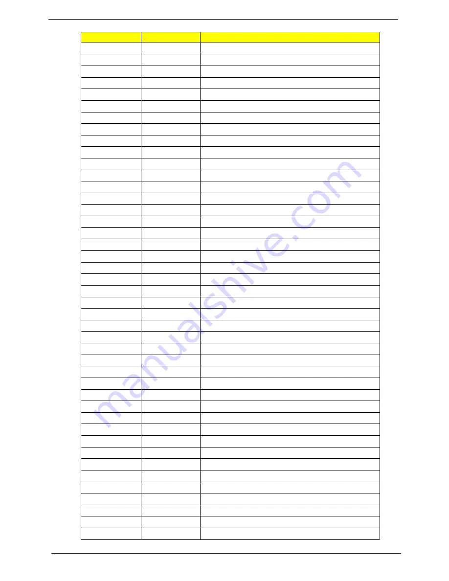
45h
POST device initialization
46h
2-1-2-3
Check ROM copyright notice
48h
Check video configuration against CMOS
49h
Initialize PCI bus and devices
4Ah
Initialize all video adapters in system
4Bh
QuietBoot start (optional)
4Ch
Shadow video BIOS ROM
4Eh
Display BIOS copyright notice
50h
Display CPU type and speed
51h
Initialize EISA board
52h
Test keyboard
54h
Set key click if enabled
58h
2-2-3-1
Test for unexpected interrupts
59h
Initialize POST display service
5Ah
Display prompt “Press F2 to enter SETUP”
5Bh
Disable CPU cache
5Ch
Test RAM between 512 and 640 KB
60h
Test extended memory
62h
Test extended memory address lines
64h
Jump to User Patch1
66h
Configure advanced cache registers
67h
Initialize Multi Processor APIC
68h
Enable external and CPU caches
69h
Setup System Management Mode (SMM) area
6Ah
Display external L2 cache size
6Bh
Load custom defaults (optional)
6Ch
Display shadow-area message
6Eh
Display possible high address for UMB recovery
70h
Display error messages
72h
Check for configuration errors
76h
Check for keyboard errors
7Ch
Set up hardware interrupt vectors
7Eh
Initialize coprocessor if present
80h
Disable onboard Super I/O ports and IRQs
81h
Late POST device initialization
82h
Detect and install external RS232 ports
83h
Configure non-MCD IDE controllers
84h
Detect and install external parallel ports
85h
Initialize PC-compatible PnP ISA devices
86h
Re-initialize onboard I/O ports
87h
Configure Motherboard Configurable Devices (optional)
88h
Initialize BIOS Area
89h
Enable Non-Maskable Interrupts (NMIs)
Code
Beeps
POST Routine Description
Содержание TRAVELMATE 8172
Страница 6: ...6 ...
Страница 49: ...Chapter 2 41 3 Insert the flash disk with the unzip file 4 Connect the adapter ...
Страница 52: ...44 Chapter 2 3 Insert the flash disk with the unzip file 4 Connect the adapter ...
Страница 55: ...Chapter 2 47 9 When the screen show Clear the SU PWs completely means the BIOS password removed completely ...
Страница 57: ...Chapter 2 49 3 Insert the flash disk with the unzip file 4 Connect the adapter ...
Страница 61: ...Chapter 2 53 11 Enter the password and the HDD lock will be released ...
Страница 63: ...Chapter 2 55 3 Insert the flash disk with the unzip file 4 Connect the adapter ...
Страница 66: ...58 Chapter 2 3 Insert the flash disk with the unzip file 4 Connect the adapter ...
Страница 67: ...Chapter 2 59 5 Log in dos mode and type dmi174r to execute the program 6 Activate the program ...
Страница 68: ...60 Chapter 2 7 Type DMI174 can check all of the function of DMI ...
Страница 70: ...62 Chapter 2 3 Insert the flash disk with the unzip file 4 Connect the adapter ...
Страница 72: ...64 Chapter 2 7 Go in to the file of MAC Insert the ßmacin bat 8 Input the MAC address ...
Страница 74: ...66 Chapter 2 3 Insert the flash disk with the unzip file 4 Connect the adapter ...
Страница 76: ...68 Chapter 2 ...
Страница 82: ...74 Chapter 3 Removing the HDD 1 Remove two 2 screws on the HDD cover ...
Страница 83: ...Chapter 3 75 2 Remove the HDD cover 3 Grasp the pull tab on the top of HDD ...
Страница 84: ...76 Chapter 3 4 Lift the HDD out of lower case 5 Remove the HDD connector ...
Страница 85: ...Chapter 3 77 6 Remove the HDD bracket 7 Remove the HDD pocket ...
Страница 86: ...78 Chapter 3 Removing the DIMM module 1 Remove two screws on the RAM cover ...
Страница 87: ...Chapter 3 79 2 Remove the RAM cover Remove the RAM cover 3 Remove the first RAM from RAM slot ...
Страница 88: ...80 Chapter 3 4 Remove the second RAM from RAM slot ...
Страница 90: ...82 Chapter 3 3 Release two screws on the wireless module 4 Remove wireless module Type Number M2 5 4 2 ...
Страница 93: ...Chapter 3 85 3 Carefully flip the keyboard over 4 Unlock the keyboard FFC ...
Страница 94: ...86 Chapter 3 5 Disconnect the keyboard FFC ...
Страница 95: ...Chapter 3 87 Removing the Upper Case 1 Unlock the touch pad FFC 2 Disconnect the Touch Pad FFC ...
Страница 96: ...88 Chapter 3 3 Unlock the power board FFC 4 Disconnect the power board FFC ...
Страница 97: ...Chapter 3 89 5 Remove two screws on the topper case Type Number M2 6 2 ...
Страница 98: ...90 Chapter 3 6 Remove all of the screws on the back of the notebook 7 Remove the upper case Type Number M2 6 9 ...
Страница 99: ...Chapter 3 91 Removing the LCD Module 1 Use the pull tab and Grab the LVDS cable 2 Disconnect the LVDS cable ...
Страница 100: ...92 Chapter 3 3 Grab the tape on the WLAN cable 4 Remove the tape on the WLAN cable ...
Страница 101: ...Chapter 3 93 5 Release WLAN cable 6 Remove 3G tape with the same method ...
Страница 102: ...94 Chapter 3 7 Release the 3G cable 8 Grab the CCD connector ...
Страница 103: ...Chapter 3 95 9 Disconnect the CCD connector 10 Grab the MIC cable ...
Страница 104: ...96 Chapter 3 11 Disconnect the MIC cable 12 Remove the screw from left hinge ...
Страница 107: ...Chapter 3 99 3 Remove the Bluetooth module ...
Страница 108: ...100 Chapter 3 Removing the Mainboard 1 Disconnect the Audio cable 2 Disconnect another side of Audio cable ...
Страница 109: ...Chapter 3 101 3 Remove the audio cable 4 Remove the screws on the power bracket Type Number M2 3 1 ...
Страница 110: ...102 Chapter 3 5 Lift the power bracket from the mainboard 6 Grab the speaker connector ...
Страница 111: ...Chapter 3 103 7 Remove the speaker connector 8 Remove four screws on the mainboard Type Number M2 3 1 ...
Страница 112: ...104 Chapter 3 9 Remove the Mainboard from button case ...
Страница 113: ...Chapter 3 105 10 Remove speaker module 11 Grab the speaker module and remove it carefully ...
Страница 114: ...106 Chapter 3 12 Disassemble the power connection 13 Disassemble fan connector ...
Страница 115: ...Chapter 3 107 14 Release four screws on the thermal module 15 Remove thermal module ...
Страница 116: ...108 Chapter 3 16 Release the connector of LED board 17 Release one screw on the LED board Type Number M2 5 4 1 ...
Страница 117: ...Chapter 3 109 18 Remove the LED board 19 Release the connector of power board ...
Страница 118: ...110 Chapter 3 20 Release the screw on the power board 21 Remove the power board Type Number M2 5 4 1 ...
Страница 120: ...112 Chapter 3 24 Remove the touch pad board ...
Страница 124: ...116 Chapter 3 5 Remove four screws on the corner of LCM Type Number M2 5 4 2 M2 3 1 ...
Страница 125: ...Chapter 3 117 6 Lift the panel out ...
Страница 126: ...118 Chapter 3 Removing the Camera Board 1 Disconnect the webcam 2 Remove webcam module ...
Страница 127: ...Chapter 3 119 Remove the Antennas 1 Release four screws from the LCD bracket ...
Страница 128: ...120 Chapter 3 2 Remove the LCD bracket 3 Remove the two tapes on the microphone cable Type Number M2 2 5 4 ...
Страница 129: ...Chapter 3 121 4 Remove the microphone 5 Remove the three tapes on the antenna cable ...
Страница 131: ...Chapter 3 123 8 Remove the LAN white antenna 9 Remove the LAN white antenna aluminum foil ...
Страница 133: ...Chapter 3 125 3 Replace the LAN black antenna aluminum foil 4 Replace the LAN black antenna ...
Страница 134: ...126 Chapter 3 5 Replace the microphone cable 6 Replace the three tapes on the antenna cable ...
Страница 135: ...Chapter 3 127 7 Lay the microphone cable in the LCD cover 8 Replace the microphone ...
Страница 136: ...128 Chapter 3 Replacing the Camera Board 1 Replace the webcam connector 2 Place the webcam in the slot ...
Страница 138: ...130 Chapter 3 Replacing LCM Module 1 Replace the bracket to the panel 2 Replace four screws on the bracket of the panel ...
Страница 139: ...Chapter 3 131 3 Replace the panel on the top case ...
Страница 142: ...134 Chapter 3 8 Replace the two screws on the panel 9 Replace two gaskets on the screws of panel ...
Страница 143: ...Chapter 3 135 Replacing the Mainboard 1 Assemble the touch pad board 2 Fasten the touch pad ...
Страница 144: ...136 Chapter 3 3 Install the three FFCs on the Touch pad board and stable it 4 Install the power board on the slot ...
Страница 145: ...Chapter 3 137 5 Fasten the screw of the power board 6 Install the FFC to the power board ...
Страница 146: ...138 Chapter 3 7 Install the LED board 8 Fasten the screw of the LED board ...
Страница 147: ...Chapter 3 139 9 Install the FFC on the LED board and stable it 10 Install the thermal module ...
Страница 148: ...140 Chapter 3 11 Fasten four screws on the thermal module 12 Replace the fan connector ...
Страница 149: ...Chapter 3 141 13 Replace the power connection 14 Insert the speaker module in the slot ...
Страница 150: ...142 Chapter 3 15 Assemble the mainboard to the bottom case 16 Assemble the mainboard to the left side of bottom case ...
Страница 151: ...Chapter 3 143 17 Fasten four screws on the mainboard 18 Insert the power bracket ...
Страница 152: ...144 Chapter 3 19 Fasten one screw on the power bracket Replacing the Panel 1 Assemble the panel to the mainboard ...
Страница 153: ...Chapter 3 145 2 Fasten two screws on the left and right hinge 3 Replace the CCD connector ...
Страница 155: ...Chapter 3 147 6 Replace the LVDS cable 7 Replace the MIC cable ...
Страница 156: ...148 Chapter 3 8 Let the 3G cable along the red line 9 Put the 3G cable into the hole in the side of mainboard ...
Страница 157: ...Chapter 3 149 10 Add two tapes on the 3G cable 11 Assemble the speaker connector ...
Страница 158: ...150 Chapter 3 12 Replace the connection of audio board 13 Replace another side connection of Audio board ...
Страница 160: ...152 Chapter 3 Replacing the Upper Case 1 Assemble the upper case ...
Страница 161: ...Chapter 3 153 2 Fasten two screws on the upper case ...
Страница 163: ...Chapter 3 155 5 Replace the speaker connection 6 Release the lock of the touch pad connection ...
Страница 164: ...156 Chapter 3 7 Connect the touch pad connection Replacing the keyboard 1 Release the lock of keyboard connection ...
Страница 168: ...160 Chapter 3 3 Insert another DIMM with the same method 4 Insert the RAM door ...
Страница 169: ...Chapter 3 161 5 Press down the RAM door 6 Fasten two screws on the RAM door ...
Страница 170: ...162 Chapter 3 Replacing HDD module 1 Insert HDD connector 2 Insert the HDD into the HDD slot ...
Страница 171: ...Chapter 3 163 3 Press down the HDD and make sure it stable 4 Replace the HDD cover and fasten two screws on it ...
Страница 172: ...164 Chapter 3 Replacing the battery 1 Insert the battery carefully 2 Lock the battery lock ...
Страница 194: ...186 Chapter 5 ...
Страница 210: ...202 Chapter 6 ...
Страница 230: ...222 Chapter 5 ...
Страница 240: ...232 Appendix C ...