Acer R751T Скачать руководство пользователя страница 7

Disassembly Procedures

1-5

Base Cover Removal

0

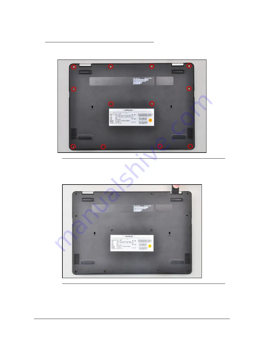
1. Remove twelve (12) screws from the base cover (

Figure 1-2

).

Figure 1-2. Base Cover Removal

2. Using a flat headed tool, carefully pry open the base cover starting from the gap 

between the left LCD hinge compartment and the base cover (

Figure 1-3

).

Figure 1-3. Base Cover Removal

Содержание R751T

Страница 1: ...Acer Chromebook Spin 11 R751T R751TN LIFECYCLE EXTENSION GUIDE ...

Страница 2: ...i Self Repair 1 1 Disassembly Procedures 1 2 Troubleshooting 1 24 FRU Field Replaceable Unit List 1 28 Check for updates yourself 1 31 Factory reset your Chromebook 1 32 ...

Страница 3: ...TE For replacement parts always use only Acer certified components in order to safeguard quality optimum system performance stability and reliability of the product NOTE NOTE Any damage to the product that occur during self repair or which has occurred as a result of a careless or unsuccessful self repair attempt is not covered by the standard product warranty Software Recovery 0 This product has ...

Страница 4: ...yourself by using a wrist grounding strap or by periodically touching an unpainted metal surface at the same time as touching a connector on the back of the computer Take off any metal objects on your arms or fingers such as bracelets rings or watches and make sure your hands are completely dry Even if your unit is unplugged there may still be some remaining electric charge If a component does not...

Страница 5: ...Disassembly Procedures 1 3 WEEE Annex VII Component 0 These components are classified as requiring selective treatment Battery pack WLAN module Touchpad module Mainboard USB board LCD panel ...

Страница 6: ...rocedures 1 Place the system on a stable work surface 2 Remove AC adapter A from the system and peripherals Figure 1 1 3 Remove the SD card from the SD card slot B Figure 1 1 4 Remove all cables from system Figure 1 1 AC Adapter Outlet SD Card Removal NOTE NOTE Make sure the system is completely powered off B A ...

Страница 7: ...twelve 12 screws from the base cover Figure 1 2 Figure 1 2 Base Cover Removal 2 Using a flat headed tool carefully pry open the base cover starting from the gap between the left LCD hinge compartment and the base cover Figure 1 3 Figure 1 3 Base Cover Removal ...

Страница 8: ... Continue prying open the base cover from the gap between the right LCD hinge compartment and the base cover Figure 1 4 Figure 1 4 Base Cover Removal 4 Remove the base cover from the system Figure 1 5 Figure 1 5 Base Cover Removal ...

Страница 9: ... top assembly Figure 1 6 2 Disconnect the battery cable B from the mainboard connector C Figure 1 6 Figure 1 6 Battery Pack Removal 3 Remove the battery pack from the system Figure 1 7 Figure 1 7 Battery Pack Removal IMPORTANT Follow local regulations for battery disposal C B A WEEE Annex VII Component Battery ...

Страница 10: ...e Battery Pack Removal 1 Find the WLAN module B on the top assembly Figure 1 8 Figure 1 8 Component Location 2 Disconnect WLAN antenna cables A from the WLAN module Figure 1 9 3 Remove one 1 screw C securing the WLAN module in place Figure 1 9 Figure 1 9 WLAN Module Removal F C B A D E C A ...

Страница 11: ...Disassembly Procedures 1 9 4 Remove the WLAN module B from the mainboard connector D Figure 1 10 Figure 1 10 WLAN Module Removal B D WEEE Annex VII Component WLAN module ...

Страница 12: ...the adhesive tape F from the touchpad connector Figure 1 11 Figure 1 11 Touchpad Tape Removal 3 Disconnect the touchpad FPC B from the touchpad connector A and the mainboard connector C then remove the touchpad FPC from the top assembly Figure 1 12 4 Remove four 4 screws D securing the touchpad module in place Figure 1 12 Figure 1 12 Touchpad FPC Removal E F C B A D ...

Страница 13: ... module from the top assembly Figure 1 13 Figure 1 13 Touchpad Module Removal CAUTION Touchpad FPC Flexible Printed Circuit can be damaged if removed while the mainboard connector and the touchpad connector are locked WEEE Annex VII Component Touchpad ...

Страница 14: ... A Figure 1 14 2 Disconnect the G sensor cable from the mainboard connector B Figure 1 14 3 Disconnect the digitizer cable from the mainboard connector C Figure 1 14 4 Disconnect the eDP cable from the mainboard connector D Figure 1 14 5 Unthread all cables from the cable guides Figure 1 14 Figure 1 14 LCD Module Removal B A B D B C A ...

Страница 15: ...urface and open the LCD module E as shown in Figure 1 15 7 Remove four 4 screws securing the LCD module in place Figure 1 15 Figure 1 15 LCD Module Removal 8 Lift and remove the LCD module away from the top assembly Figure 1 16 Figure 1 16 LCD Module Removal E ...

Страница 16: ...1 14 Disassembly Procedures CAUTION Make sure all cables and antennas are unthread from the cable guides to avoid damage removal ...

Страница 17: ...efer to Figure 1 18 4 Disconnect the 40 pin USB board FPC from the mainboard connector C Refer to Figure 1 18 5 Disconnect the second camera module cable from the mainboard connector E Refer to Figure 1 18 6 Disconnect the keyboard FPC from the mainboard connector A Refer to Figure 1 18 7 Disconnect the touchpad FPC from the mainboard connector F Refer to Figure 1 18 8 Disconnect the speaker cable...

Страница 18: ...move four 4 screws H securing the mainboard in place Figure 1 18 Figure 1 18 Mainboard Removal 10 Remove the mainboard from the top assembly Figure 1 19 Figure 1 19 Mainboard Removal F E B C A G H H WEEE Annex VII Component Mainboard ...

Страница 19: ...bly Procedures 1 17 Figure 1 20 Mainboard IMPORTANT Circuit boards 10 cm have been highlighted with a yellow rectangle as shown in Figure 1 20 Remove the circuit board and follow local regulations for disposal ...

Страница 20: ...ctor A and remove the 30 pin USB board FPC Figure 1 21 3 Disconnect the 40 pin USB board FPC F from the mainboard connector G and the USB board connector E and remove the 40 pin USB board FPC Figure 1 21 4 Remove one 1 screw H securing the USB board in place Figure 1 21 Figure 1 21 USB Board Removal 5 Remove the USB board from the top assembly Figure 1 22 Figure 1 22 USB Board Removal H C D G B A ...

Страница 21: ...Disassembly Procedures 1 19 CAUTION USB board FPC Flexible Printed Circuit can be damaged if removed while the mainboard connector and USB board connector are locked ...

Страница 22: ...he eDP cable from the LCD hinge compartment A Figure 1 23 Figure 1 23 LCD Panel Removal 2 Using a flat headed tool pry open from the gap in one of the corners then slide the tool through the top side of the LCD module to release the LCD panel from the latches Figure 1 24 Figure 1 24 LCD Panel Removal A ...

Страница 23: ...ssembly Procedures 1 21 3 Continue along the left side of the LCD module Figure 1 25 Figure 1 25 LCD Panel Removal 4 Continue along the right side of the LCD module Figure 1 26 Figure 1 26 LCD Panel Removal ...

Страница 24: ...1 22 Disassembly Procedures 5 Lift and remove the LCD panel from the LCD cover Figure 1 27 Figure 1 27 LCD Panel Removal WEEE Annex VII Component LCD panel ...

Страница 25: ... module Speaker module Mainboard and USB board have been disassembled prior removing the top assembly NOTE NOTE The keyboard is included as part of the top assembly and can not be disassembled In the event that the keyboard can no longer be used replace the entire top assembly Figure 1 28 Top Assembly ...

Страница 26: ...more help contact Google support When to recover 0 You might want to recover if You see this error message Chrome OS is missing or damaged You ve tried other troubleshooting steps and nothing has fixed your issue You ve asked the experts in our help forum for help fixing your issue and they recommend recovery What you need to get started 0 The Chromebook with the Chrome OS is missing or damaged er...

Страница 27: ...d this number look at the bottom of the error message on your Chromebook screen 5 Click Continue 6 Insert your USB flash drive or SD card into the computer 7 In the dropdown menu choose the USB flash drive or SD card you inserted 8 Click Continue 9 Click Create now 10 When you see a message saying that your recovery media is ready remove the USB flash drive or SD card from the computer Step 3 Ente...

Страница 28: ...n to open the popup 6 Optional If you use the extension frequently you can pin it Optional Reuse your USB flash drive or SD card After recovering your Chromebook you ll need to erase the recovery media if you want to reuse your USB flash drive or SD card to store other files To erase the recovery media 1 On your computer open Chrome 2 At the top right click Extensions 3 To launch the extension pop...

Страница 29: ...at you inserted the USB drive or SD card that you used to create recovery media If you re using the correct storage device but still see this error the storage device might not be working properly 1 Erase the storage device then try recovery again 2 Try using a different USB flash drive or SD card to recover Some USB flash drives and SD cards don t work well with recovery If you re still having pr...

Страница 30: ...1 28 FRU Field Replaceable Unit List FRU Field Replaceable Unit List Please contact your local service center to find out how to obtain the part or replace your device ...

Страница 31: ... System Exploded Diagram Table 1 1 System Exploded Diagram No Description No Description 1 Base Cover 6 2nd Camera Cable 2 WLAN Module 7 Battery Pack 3 USB Board 8 Top Assembly 4 30 pin USB Board FPC 9 LCD Module 5 40 pin USB Board FPC 10 Mainboard 4 10 5 6 8 9 3 2 1 7 ...

Страница 32: ... 2 LCD Assembly Exploded Diagram No Description No Description 1 LCD Panel LCD Bezel 7 G Sensor Board 2 eDP Cable 8 Microphone Board 3 Screw x 2 9 Camera Module 4 Screw x 6 10 G Sensor Cable 5 LCD Hinge L 11 LCD Hinge R 6 LCD Cover 12 WLAN Antenna MAIN and AUX 1 2 3 7 8 5 6 4 9 10 11 12 ...

Страница 33: ...t the bottom right select the time 4 Select Settings 5 At the bottom of the left panel select About Chrome OS 6 Under Google Chrome OS you ll find which version of the Chrome operating system your Chromebook uses 7 Select Check for updates 8 If your Chromebook finds a software update it will start to download automatically ...

Страница 34: ...our Chromebook 2 Press and hold Ctrl Alt Shift r 3 Select Restart 4 In the box that appears select Powerwash Continue 5 Follow the steps that appear and sign in with your Google Account NOTE NOTE The account you sign in with after you reset your Chromebook will be the owner account ...

Отзывы: