1-14
Disassembly Procedures
CAUTION
:
!
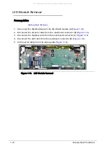
Make sure all cables and antennas are unthread from the cable guides to avoid damage removal.
All manuals and user guides at all-guides.com
Страница 1: ...Acer Chromebook Spin 11 R751T R751TN LIFECYCLE EXTENSION GUIDE All manuals and user guides at all guides com...
Страница 2: ...epair 1 1 Disassembly Procedures 1 2 Troubleshooting 1 24 FRU Field Replaceable Unit List 1 28 Check for updates yourself 1 31 Factory reset your Chromebook 1 32 All manuals and user guides at all gui...
Страница 3: ...always use only Acer certified components in order to safeguard quality optimum system performance stability and reliability of the product NOTE NOTE Any damage to the product that occur during self...
Страница 4: ...t grounding strap or by periodically touching an unpainted metal surface at the same time as touching a connector on the back of the computer Take off any metal objects on your arms or fingers such as...
Страница 5: ...ures 1 3 WEEE Annex VII Component 0 These components are classified as requiring selective treatment Battery pack WLAN module Touchpad module Mainboard USB board LCD panel All manuals and user guides...
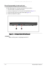
Страница 6: ...stem on a stable work surface 2 Remove AC adapter A from the system and peripherals Figure 1 1 3 Remove the SD card from the SD card slot B Figure 1 1 4 Remove all cables from system Figure 1 1 AC Ada...
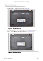
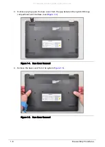
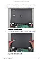
Страница 7: ...e base cover Figure 1 2 Figure 1 2 Base Cover Removal 2 Using a flat headed tool carefully pry open the base cover starting from the gap between the left LCD hinge compartment and the base cover Figur...
Страница 8: ...e base cover from the gap between the right LCD hinge compartment and the base cover Figure 1 4 Figure 1 4 Base Cover Removal 4 Remove the base cover from the system Figure 1 5 Figure 1 5 Base Cover R...
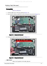
Страница 9: ...2 Disconnect the battery cable B from the mainboard connector C Figure 1 6 Figure 1 6 Battery Pack Removal 3 Remove the battery pack from the system Figure 1 7 Figure 1 7 Battery Pack Removal IMPORTA...
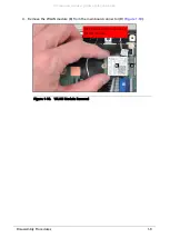
Страница 10: ...Find the WLAN module B on the top assembly Figure 1 8 Figure 1 8 Component Location 2 Disconnect WLAN antenna cables A from the WLAN module Figure 1 9 3 Remove one 1 screw C securing the WLAN module...
Страница 11: ...bly Procedures 1 9 4 Remove the WLAN module B from the mainboard connector D Figure 1 10 Figure 1 10 WLAN Module Removal B D WEEE Annex VII Component WLAN module All manuals and user guides at all gui...
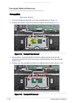
Страница 12: ...the touchpad connector Figure 1 11 Figure 1 11 Touchpad Tape Removal 3 Disconnect the touchpad FPC B from the touchpad connector A and the mainboard connector C then remove the touchpad FPC from the...
Страница 13: ...embly Figure 1 13 Figure 1 13 Touchpad Module Removal CAUTION Touchpad FPC Flexible Printed Circuit can be damaged if removed while the mainboard connector and the touchpad connector are locked WEEE A...
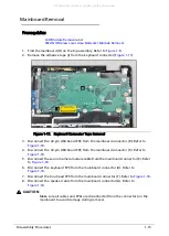
Страница 14: ...ect the G sensor cable from the mainboard connector B Figure 1 14 3 Disconnect the digitizer cable from the mainboard connector C Figure 1 14 4 Disconnect the eDP cable from the mainboard connector D...
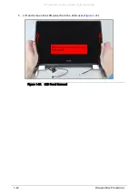
Страница 15: ...module E as shown in Figure 1 15 7 Remove four 4 screws securing the LCD module in place Figure 1 15 Figure 1 15 LCD Module Removal 8 Lift and remove the LCD module away from the top assembly Figure 1...
Страница 16: ...1 14 Disassembly Procedures CAUTION Make sure all cables and antennas are unthread from the cable guides to avoid damage removal All manuals and user guides at all guides com...
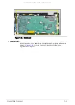
Страница 17: ...sconnect the 40 pin USB board FPC from the mainboard connector C Refer to Figure 1 18 5 Disconnect the second camera module cable from the mainboard connector E Refer to Figure 1 18 6 Disconnect the k...
Страница 18: ...uring the mainboard in place Figure 1 18 Figure 1 18 Mainboard Removal 10 Remove the mainboard from the top assembly Figure 1 19 Figure 1 19 Mainboard Removal F E B C A G H H WEEE Annex VII Component...
Страница 19: ...re 1 20 Mainboard IMPORTANT Circuit boards 10 cm have been highlighted with a yellow rectangle as shown in Figure 1 20 Remove the circuit board and follow local regulations for disposal All manuals an...
Страница 20: ...pin USB board FPC Figure 1 21 3 Disconnect the 40 pin USB board FPC F from the mainboard connector G and the USB board connector E and remove the 40 pin USB board FPC Figure 1 21 4 Remove one 1 screw...
Страница 21: ...embly Procedures 1 19 CAUTION USB board FPC Flexible Printed Circuit can be damaged if removed while the mainboard connector and USB board connector are locked All manuals and user guides at all guide...
Страница 22: ...D hinge compartment A Figure 1 23 Figure 1 23 LCD Panel Removal 2 Using a flat headed tool pry open from the gap in one of the corners then slide the tool through the top side of the LCD module to rel...
Страница 23: ...3 Continue along the left side of the LCD module Figure 1 25 Figure 1 25 LCD Panel Removal 4 Continue along the right side of the LCD module Figure 1 26 Figure 1 26 LCD Panel Removal All manuals and u...
Страница 24: ...22 Disassembly Procedures 5 Lift and remove the LCD panel from the LCD cover Figure 1 27 Figure 1 27 LCD Panel Removal WEEE Annex VII Component LCD panel All manuals and user guides at all guides com...
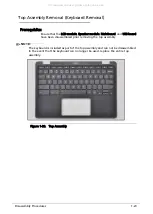
Страница 25: ...ainboard and USB board have been disassembled prior removing the top assembly NOTE NOTE The keyboard is included as part of the top assembly and can not be disassembled In the event that the keyboard...
Страница 26: ...support When to recover 0 You might want to recover if You see this error message Chrome OS is missing or damaged You ve tried other troubleshooting steps and nothing has fixed your issue You ve aske...
Страница 27: ...e bottom of the error message on your Chromebook screen 5 Click Continue 6 Insert your USB flash drive or SD card into the computer 7 In the dropdown menu choose the USB flash drive or SD card you ins...
Страница 28: ...tional If you use the extension frequently you can pin it Optional Reuse your USB flash drive or SD card After recovering your Chromebook you ll need to erase the recovery media if you want to reuse y...
Страница 29: ...drive or SD card that you used to create recovery media If you re using the correct storage device but still see this error the storage device might not be working properly 1 Erase the storage device...
Страница 30: ...U Field Replaceable Unit List FRU Field Replaceable Unit List Please contact your local service center to find out how to obtain the part or replace your device All manuals and user guides at all guid...
Страница 31: ...Table 1 1 System Exploded Diagram No Description No Description 1 Base Cover 6 2nd Camera Cable 2 WLAN Module 7 Battery Pack 3 USB Board 8 Top Assembly 4 30 pin USB Board FPC 9 LCD Module 5 40 pin US...
Страница 32: ...Diagram No Description No Description 1 LCD Panel LCD Bezel 7 G Sensor Board 2 eDP Cable 8 Microphone Board 3 Screw x 2 9 Camera Module 4 Screw x 6 10 G Sensor Cable 5 LCD Hinge L 11 LCD Hinge R 6 LC...
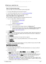
Страница 33: ...t the time 4 Select Settings 5 At the bottom of the left panel select About Chrome OS 6 Under Google Chrome OS you ll find which version of the Chrome operating system your Chromebook uses 7 Select Ch...
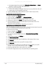
Страница 34: ...nd hold Ctrl Alt Shift r 3 Select Restart 4 In the box that appears select Powerwash Continue 5 Follow the steps that appear and sign in with your Google Account NOTE NOTE The account you sign in with...