1-14
Hardware Specifications and Configurations
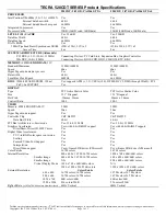
Keyboard
0
The keyboard contains an overlay numeric keys, inverted “T” cursor key, Windows® key,
Application key, function lock keys, and hotkeys controlling various computer features.
Figure 1-7.
Keyboard
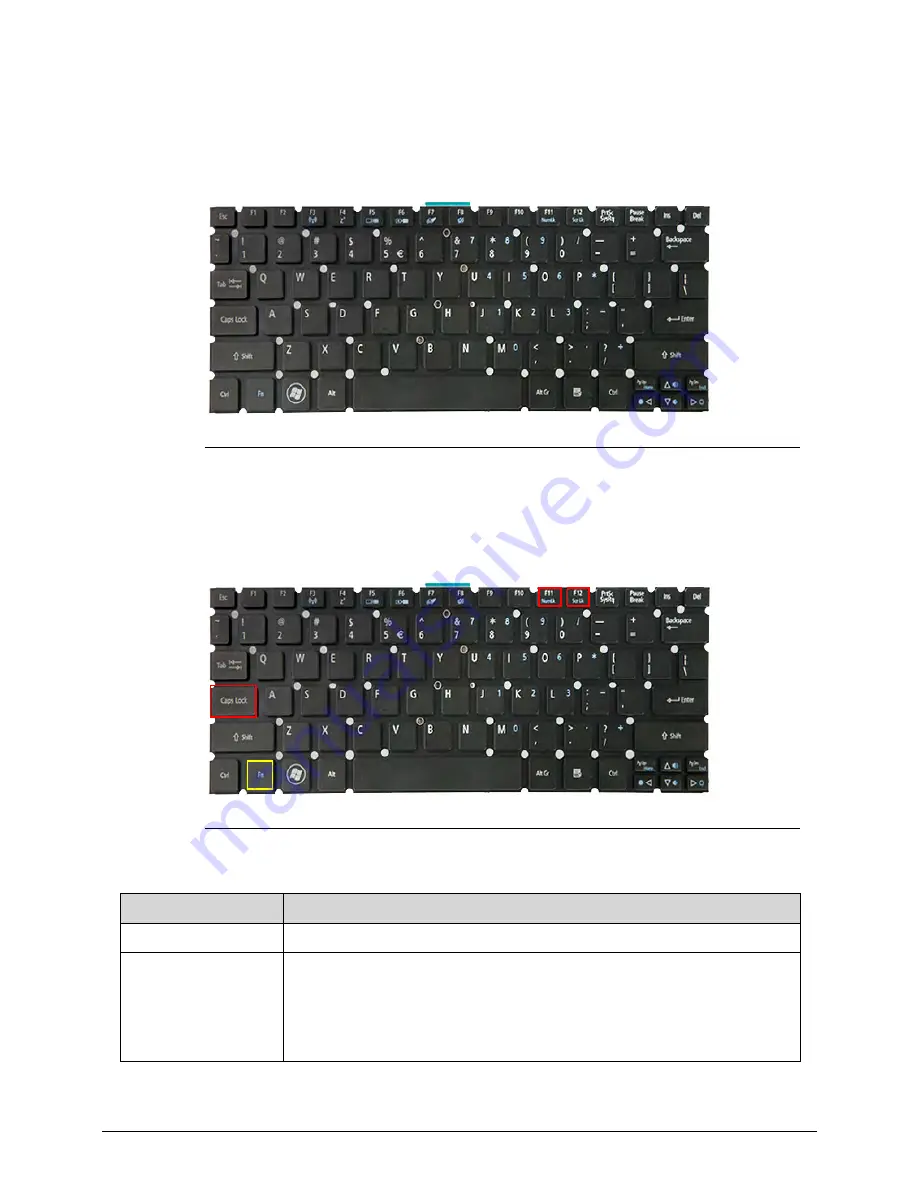
Lock Keys
0
The keyboard has three lock keys which the user can toggle on and off.
Figure 1-8.
Keyboard Lock Keys
Table 1-8.
Keyboard Lock Keys
Lock Key
Description
Caps Lock
When On, all typed alphabetic characters appears in uppercase.
Num Lock
Fn
+
F11
Off by default. When On, the overlay numeric keys acts as a numeric
keypad. If an external keyboard or keypad is present, the Num Lock will
have the following definitions:
When On, the system boots with external keyboard/keypad Num Lock
status On. Internal keyboard overlay numeric keys are disabled.
Содержание Aspire S3-391
Страница 1: ...Aspire S3 MS2346 SERVICEGUIDE...
Страница 9: ...CHAPTER 1 Hardware Specifications...
Страница 39: ...CHAPTER 2 System Utilities...
Страница 55: ...CHAPTER 3 Machine Maintenance...
Страница 57: ...3 3 Replacing the Battery Pack 3 71 Replacing the Lower Case 3 74...
Страница 58: ...3 4...
Страница 68: ...3 14 Machine Maintenance 6 Disconnect the speaker s cable from the mainboard Figure 3 13 Speaker Cable...
Страница 86: ...3 32 Machine Maintenance 5 Detach the thermal module from the mainboard Figure 3 47 Thermal Module...
Страница 108: ...3 54 Machine Maintenance 3 Connect the thermal module fan cable to the mainboard Figure 3 87 Fan Cable...
Страница 131: ...CHAPTER 4 Troubleshooting...
Страница 160: ...4 30 Troubleshooting...
Страница 161: ...CHAPTER 5 Jumper and Connector Locations...
Страница 168: ...5 8 Jumper and Connector Locations...
Страница 169: ...CHAPTER 6 FRU List...
Страница 170: ...6 2 Aspire S3 MS2346 Exploded Diagrams 6 4 Main Assembly 6 4 FRU List 6 6...
Страница 182: ...6 14 FRU Field Replaceable Unit List...
Страница 183: ...CHAPTER 7 Test Compatible Components...
Страница 184: ...7 2 Microsoft Windows 7 Environment Test 7 3...
Страница 190: ...7 8 Test Compatible Components...
Страница 191: ...CHAPTER 8 Online Support Information...
Страница 192: ...8 2 Online Support Information 8 3...
Страница 194: ...8 4...