56
Chapter 5
Connecting Optional Devices
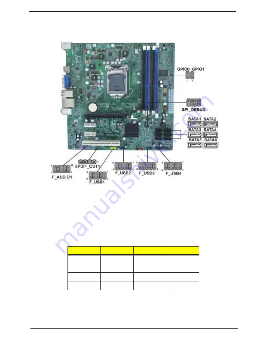
Refer to the following for information on connecting the motherboard’s optional
devices:
SATA1~6: Serial ATA connectors
These connectors are used to support the new Serial ATA devices for the highest data
transfer rates (3.0 Gb/s), simpler disk drive cabling and easier PC assembly. It eliminates
limitations of the current Parallel ATA interface. But maintains register compatibility
and software compatibility with Parallel ATA.
F_USB1~4: Front Panel USB headers
The motherboard has four USB ports installed on the rear edge I/O port array.
Additionally, some computer cases have USB ports at the front of the case. If you
Pin
Signal Name
?Pin
Signal Name
1
Ground
2
TX+
3 TX-
4 Ground
5 RX-
6 RX+
7 Ground
-
-
Содержание ASPIRE M5910(G)
Страница 1: ...Acer Aspire M5910 G Service Guide PRINTED IN TAIWAN ...
Страница 12: ...4 Chapter 1 Block Diagram ...
Страница 40: ...Chapter 3 32 Removing the TV Card 1 Gently pull the TV card to remove it from the mainboard ...
Страница 41: ...33 Chapter 3 Removing the Mode Card 1 Gently pull the Mode card to remove it from the mainboard ...
Страница 53: ...45 Chapter 3 2 Lift the board from the chassis 3 Remove the RTC battery ...
Страница 61: ...Chapter 5 53 M B Placement Jumper and Connector Information Chapter 5 ...


