


System Utilities
2-5
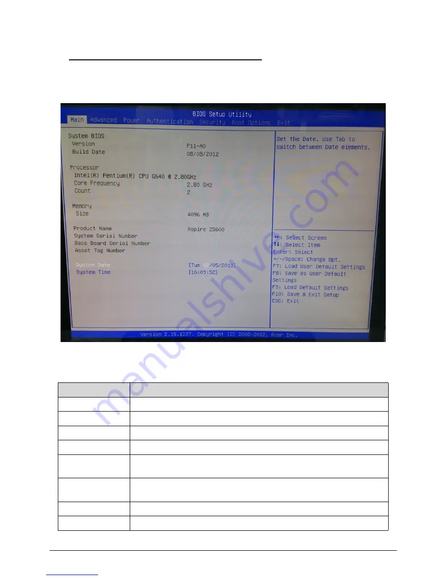
BIOS Setup Utility
0
Main
0
Table 2-1.
Parameter
Description
System BIOS
Version and Build Date of BIOS installed on the system.
Processor
Intel series, Core Frequency and Count of CPU installed on the system.
Memory
Total size of system memory installed on the system.
Product Name
Product name of the system.
System Serial
Number
Serial number of the system.
Base Board Serial
Number
Serial number of the base board.
Asset Tag Number
Asset Tag number of this system.
System Date
Set the Date. Use Tab to switch between Date elements.
Содержание Aspire AZS600_P
Страница 1: ...Acer AZS600_Pt AZS600_P SERVICEGUIDE ...
Страница 4: ...iv ...
Страница 8: ...ii viii ...
Страница 9: ...CHAPTER 1 Hardware Specifications ...
Страница 29: ...Hardware Specifications and Configurations 1 21 M B Placement 0 ...
Страница 32: ...1 24 Hardware Specifications and Configurations Block Diagram 0 ...
Страница 33: ...CHAPTER 2 System Utilities ...
Страница 61: ...System Utilities 2 29 1 Check ME status with MEInfo Utility and ManufacturingMode is Disabled ...
Страница 68: ...2 36 System Utilities 10 Select Yes and press Enter key 11 Select Save Exit Setup and press Enter key ...
Страница 69: ...System Utilities 2 37 12 Select Yes and press Enter key 13 Flash BIOS is finished ...
Страница 72: ...2 40 System Utilities ...
Страница 77: ...CHAPTER 3 System Disassembly and Assembly ...
Страница 80: ...3 4 ...
Страница 83: ...3 7 Disassembly Flowchart 0 Figure 3 1 Disassembly Flowchart ...
Страница 85: ...3 9 Table 3 2 Screws Step Screw Quantity Screw Type Stand Removal M4 6 3 ...
Страница 87: ...3 11 Figure 3 6 ODD Bezel ...
Страница 94: ...3 18 Figure 3 18 VESA Support Bracket ...
Страница 96: ...3 20 Figure 3 21 HDD Module 4 Remove 4 screws to separate HDD from the cage Figure 3 22 HDD Module ...
Страница 99: ...3 23 Figure 3 27 ODD Module 4 Remove 4 screws to separate the ODD from the cage Figure 3 28 ODD Module ...
Страница 100: ...3 24 Figure 3 29 ODD Module Table 3 9 Screws Step Screw Quantity Screw Type ODD Removal M2 2 4 ...
Страница 103: ...3 27 Figure 3 34 Speaker ...
Страница 105: ...3 29 Figure 3 37 Heatsink ...
Страница 108: ...3 32 Figure 3 42 Convert Board ...
Страница 110: ...3 34 Figure 3 45 OSD Board ...
Страница 112: ...3 36 Figure 3 48 VGA Card ...
Страница 114: ...3 38 Figure 3 51 VGA Bracket ...
Страница 116: ...3 40 Figure 3 54 WLAN Card Figure 3 55 WLAN Card ...
Страница 118: ...3 42 Remove the CPU 0 1 Remove CPU from the LGA socket of motherboard Figure 3 58 CPU Figure 3 59 CPU ...
Страница 126: ...3 50 Table 3 23 Screws Step Screw Quantity Screw Type Front Stand Middle Bracket Removal M3 6 4 ...
Страница 129: ...3 53 Remove the Cushion Tape 0 1 Tear off 2 pieces of cushion tape from 2 bulges of base pan Figure 3 79 Cushion Tape ...
Страница 130: ...3 54 Remove the Thermal Pads 0 1 Tear off 4 thermal pads from the bulges of base pan Figure 3 80 Thermal Pads ...
Страница 131: ...3 55 Remove the LVDS Cable 0 1 Release the latches to disconnect LVDS cable from LCD panel Figure 3 81 LVDS Cable ...
Страница 133: ...3 57 Figure 3 84 Base Pan ...
Страница 136: ...3 60 Remove the IR Cable 0 1 Lift to remove the IR cable from front bezel Figure 3 89 IR Cable ...
Страница 138: ...3 62 Reassembly Procedure 0 Reassembly Flowchart 0 Figure 3 92 Reassembly Flowchart ...
Страница 140: ...3 64 Table 3 26 Screws Step Screw Quantity Screw Type Front Bezel Replacement M3 5 10 ...
Страница 149: ...3 73 Replace the Cushion Tape 0 1 Adhere 2 cushion tapes on 2 bulges of base pan Figure 3 108 Cushion Tape ...
Страница 151: ...3 75 Figure 3 111 Base Pan Table 3 28 Screws Step Screw Quantity Screw Type Base Pan Replacement M3 5 18 ...
Страница 156: ...3 80 Table 3 31 Screws Step Screw Quantity Screw Type Front Stand Left Bracket Replacement M3 5 3 M3 6 2 ...
Страница 158: ...3 82 Figure 3 122 Replace CPU Step 2 Figure 3 123 Replace CPU Step 3 ...
Страница 159: ...3 83 Figure 3 124 Replace CPU Step 4 Figure 3 125 Replace CPU Step 5 ...
Страница 160: ...3 84 Figure 3 126 Replace CPU Step 6 ...
Страница 165: ...3 89 Figure 3 133 WLAN Card ...
Страница 167: ...3 91 Figure 3 136 VGA Holder ...
Страница 171: ...3 95 Figure 3 143 Conductive Fabric ...
Страница 174: ...3 98 Figure 3 148 ODD Module Table 3 38 Screws Step Screw Quantity Screw Type ODD Module Replacement M3 5 1 ...
Страница 180: ...3 104 Figure 3 159 Heatsink Table 3 41 Screws Step Screw Quantity Screw Type Heatsink Replacement M3 5 1 ...
Страница 188: ...3 112 Table 3 47 Screws Step Screw Quantity Screw Type PCT Touch Cable Replacement M3 5 1 ...
Страница 193: ...3 117 Figure 3 179 ODD Bezel ...
Страница 195: ...CHAPTER 4 Troubleshooting ...
Страница 204: ...4 10 Troubleshooting 3 Once firmware update is completed press any key to reboot the system ...
Страница 210: ...4 16 Troubleshooting Click the 25 points shown in the screen with the touch pen ...
Страница 213: ...Troubleshooting 4 19 ...
Страница 218: ...4 24 Troubleshooting ...
Страница 219: ...CHAPTER 5 Jumper and Connector Locations ...
Страница 220: ...5 2 Jumper Setting 5 5 Setting Jumper 5 5 ...
Страница 221: ...Jumper and Connector Locations 5 3 Jumper and Connector Locations ...
Страница 224: ...5 6 Jumper and Connector Locations ...
Страница 225: ...CHAPTER 6 FRU List ...
Страница 226: ...6 2 AZS600_Pt Exploded Diagrams 6 4 FRU List 6 7 ...


