


Machine Maintenance Procedures
3-35
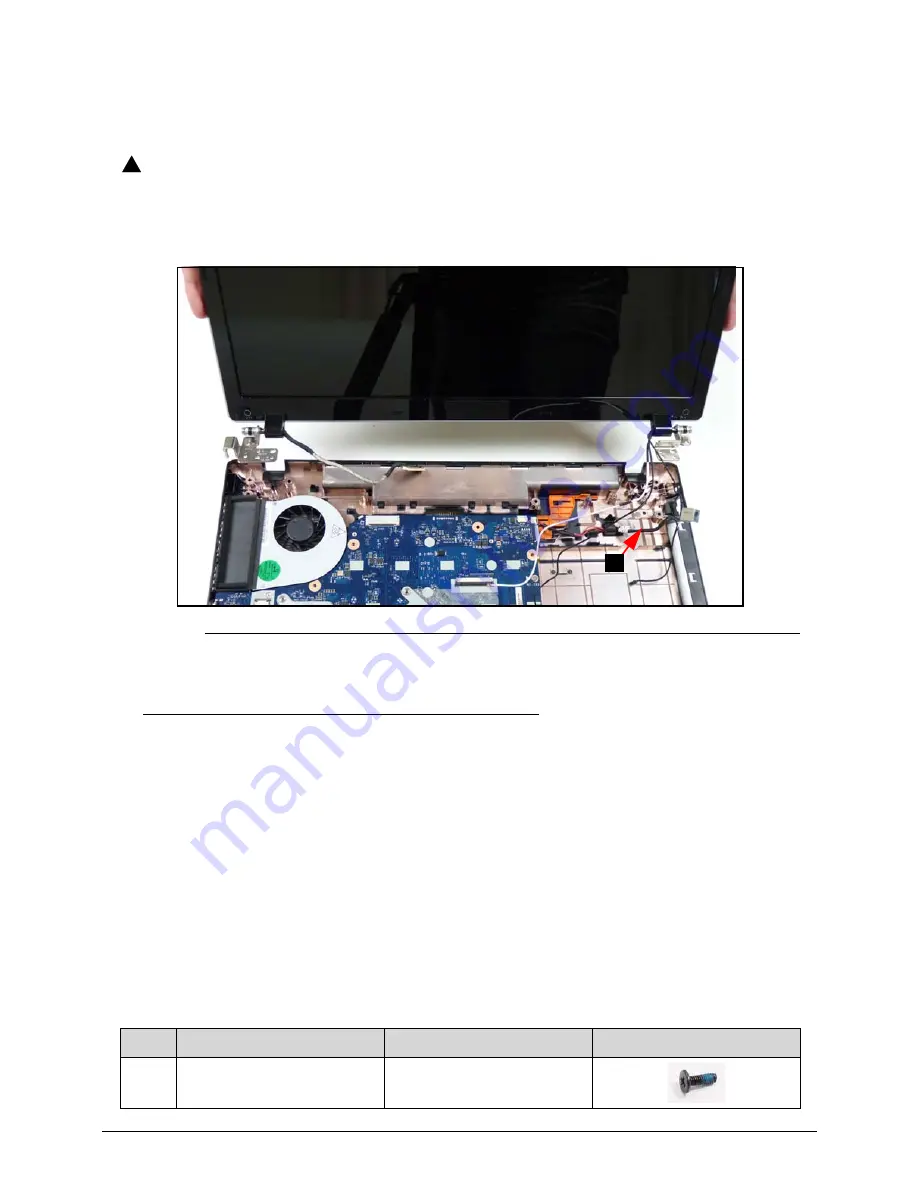
4.
Release microphone cable and WLAN antenna cables from cable guides
(
Figure 3-31
).
5.
Disconnect LVDS (E) and microphone cable (F) (
Figure 3-29).
6.
Remove five (5) screws (H) from LCD module hinges.
CAUTION
:
!
Make sure all cables are pulled back and away from device to avoid damage
during removal.
7.
Remove LCD module from lower cover (
Figure 3-31)
.
Figure 3-31.
LCD Module Removal
LCD Module Installation
0
1.
Install and secure LCD module with five (5) screws (H) to chassis (
Figure 3-29
)
.
2.
Connect LVDS (E) and microphone cable (F) (
Figure 3-29
)
3.
Feed WLAN antenna cables through lower cover opening (B) (
Figure 3-29
and
Figure 3-30
).
4.
Place WLAN antenna cables and microphone cable in cable guides.
5.
Connect DC-IN cable (C) to slot (D) by covering microphone cable and WLAN antenna
cables (
Figure 3-29
and
Figure 3-31
).
6.
Place computer upper cover facing surface.
7.
Connect WLAN antenna cables to WLAN module connectors (
Figure 3-9
and
WLAN
Module Installation
).
8.
Install speakers.
9.
Install LAN module.
ID
Size
Quantity
Screw Type
H
M2.5*6
5
C
Содержание Aspire 7750
Страница 1: ...Aspire 7750 7750G SERVICEGUIDE ...
Страница 10: ...x ...
Страница 11: ...CHAPTER 1 Hardware Specification ...
Страница 14: ...1 4 ...
Страница 32: ...1 22 Hardware Specifications and Configurations System Block Diagram Figure 1 10 System Block Diagram ...
Страница 56: ...1 46 Hardware Specifications and Configurations ...
Страница 57: ...CHAPTER 2 System Utilities ...
Страница 79: ...CHAPTER 3 Machine Maintenance ...
Страница 82: ...3 4 ...
Страница 122: ...3 44 Machine Maintenance Procedures ...
Страница 123: ...CHAPTER 4 Troubleshooting ...
Страница 149: ...CHAPTER 5 Jumper and Connector Locations ...
Страница 156: ...5 8 Jumper and Connector Locations ...
Страница 157: ...CHAPTER 6 FRU List ...
Страница 158: ...6 2 Exploded Diagrams 6 4 FRU List 6 6 Screw List 6 23 ...
Страница 180: ...6 24 FRU Field Replaceable Unit List ...
Страница 181: ...CHAPTER 7 Model Definition and Configuration ...
Страница 182: ...7 2 Aspire 7750 7750G 7 3 ...
Страница 253: ...CHAPTER 8 Test Compatible Components ...
Страница 254: ...8 2 Microsoft Windows 7 Environment Test 8 4 ...
Страница 270: ...8 18 Test Compatible Components ...
Страница 271: ...CHAPTER 9 Online Support Information ...
Страница 272: ...9 2 Introduction 9 3 ...
Страница 274: ...9 4 Online Support Information ...


