


Chapter 2
37
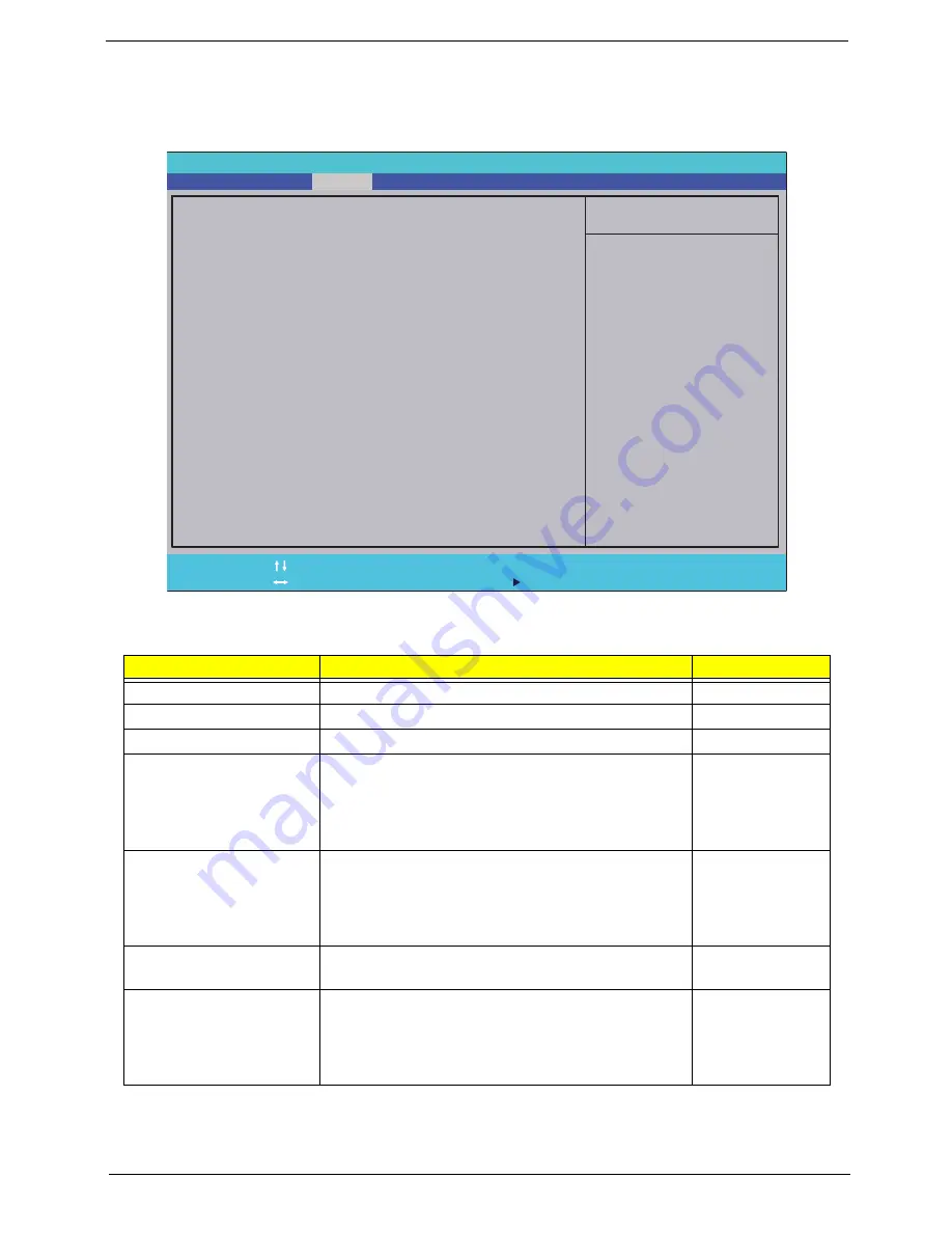
Security
The Security screen contains parameters that help safeguard and protect your computer from unauthorized
use.
The table below describes the parameters in this screen. Settings in
boldface
are the default and suggested
parameter settings.
NOTE:
When you are prompted to enter a password, you have three tries before the system halts. Don’t forget
the password. If you forget the password, you may have to reset the computer.
Parameter
Description
Option
Supervisor Password Is
Shows the setting of the Supervisor password
Clear
or Set
User Password Is
Shows the setting of the user password.
Clear
or Set
HDD Password Is
Shows the setting of the user password
Clear
or Set
Set Supervisor Password
Press Enter to set the supervisor password. When
set, this password protects the BIOS Setup Utility
from unauthorized access. The user can not either
enter the Setup menu nor change the value of
parameters.
N/A
Set User Password
Press Enter to set the user password. When user
password is set, this password protects the BIOS
Setup Utility from unauthorized access. The user can
enter Setup menu only and does not have right to
change the value of parameters.
N/A
Set HDD Password
Press Enter to set the HDD password. When set this
protects the HDD from unauthorized access.
N/A
Password on boot
Defines whether a password is required or not while
the events defined in this group happened. The sub-
options all require the Supervisor password for
changes and should be grayed out if the user
password was used to enter setup.
Disabled
or
Enabled
I t e m S p e c i f i c H e l p
I n s t a l l o r C h a n g e t h e
p a s s w o r d a n d t h e l e n g t h
o f p a s s w o r d m u s t b e
g r e a t e r t h a n o n e w o r d .
F 1
E S C
H e l p
E x i t
S e l e c t I t e m
S e l e c t M e n u
C h a n g e Va l u e s
S e l e c t
S u b M e n u
E n t e r
F 9
F 10
S e t u p D e f a u l t
S a v e a n d E x i t
C l e a r
C l e a r
C l e a r
[ E n t e r ]
[ E n t e r ]
[ E n t e r ]
[ D i s a b l e d ]
C l e a r
C l e a r
C l e a r
[ E n t e r ]
[ E n t e r ]
[ E n t e r ]
[ D i s a b l e d ]
S u p e r v i s o r P a s s w o r d I s :
U s e r P a s s w o r d I s :
H D D P a s s w o r d I s :
S e t S u p e r v i s o r P a s s w o r d
S e t U s e r P a s s w o r d
S e t H D D P a s s w o r d
P a s s w o r d o n b o o t :
S u p e r v i s o r P a s s w o r d I s :
U s e r P a s s w o r d I s :
H D D P a s s w o r d I s :
S e t S u p e r v i s o r P a s s w o r d
S e t U s e r P a s s w o r d
S e t H D D P a s s w o r d
P a s s w o r d o n b o o t :
F 5 / F 6
Information
Main
Boot
Exit
Security
P h o e n i x S e c u r e C o r e ( t m ) S e t u p U t i l i t y
Содержание ASPIRE 5625
Страница 6: ...VI ...
Страница 10: ...X Table of Contents ...
Страница 42: ...32 Chapter 1 ...
Страница 67: ...Chapter 3 57 4 Lift the base door out and away ...
Страница 72: ...62 Chapter 3 5 Pull the WLAN module out and away ...
Страница 80: ...70 Chapter 3 8 Flip the keyboard over 9 Detach the keyboard FPC a Unlock the FPC b Pull the keyboard away a b ...
Страница 86: ...76 Chapter 3 4 Unlock and disconnect the switch board FFC ...
Страница 88: ...78 Chapter 3 4 Lift the power board away ...
Страница 93: ...Chapter 3 83 14 Lift the LCD module out of the assembly ...
Страница 95: ...Chapter 3 85 4 Lift away the USB board 5 Unlock and remove the USB board FFC from the mainboard ...
Страница 104: ...94 Chapter 3 4 Lift the power cable assembly out of the chassis 5 Lift the power cable connector out of the bracket ...
Страница 107: ...Chapter 3 97 4 Pry open the bottom corners and along the bottom edge 5 Lift the bezel off the module ...
Страница 111: ...Chapter 3 101 7 Disconnect the FPC cable ...
Страница 114: ...104 Chapter 3 8 Remove the cables from the retention guides 9 Pry the antenna off the casing ...
Страница 119: ...Chapter 3 109 7 Lay the cables along the retention guides ...
Страница 125: ...Chapter 3 115 3 Press down on the bezel edge working simultaneously around the edges to the bottom ...
Страница 130: ...120 Chapter 3 2 Using a flat bladed screw driver rotate the CPU locking screw 180 clockwise to secure the CPU in place ...
Страница 134: ...124 Chapter 3 4 Connect and lock the USB card FFC to the mainboard ...
Страница 136: ...126 Chapter 3 4 Connect the Bluetooth module cable to the main board ...
Страница 140: ...130 Chapter 3 10 Press the LVDS connector left and right adhesive tabs down onto the mainboard ...
Страница 146: ...136 Chapter 3 7 Connect and lock the button board FFC ...
Страница 152: ...142 Chapter 3 4 Grasp the tab and slide the HDD firmly into the docking connector ...
Страница 154: ...144 Chapter 3 Replacing the ODD Module 1 Replace the ODD bezel 2 Replace the ODD bracket ...
Страница 158: ...148 Chapter 3 ...
Страница 176: ...166 Chapter 5 Mainboard Bottom View VGA HDMI LAN USB MIC Headphone SPDIF Batter DC in ODD HDD FAN WLAN ...
Страница 178: ...168 Chapter 5 ...
Страница 190: ...180 Chapter 6 ...
Страница 227: ...Appendix B 217 Modem External USB Lite LSI modem LC MOD00 001 Part Description Part ...
Страница 228: ...218 Appendix B ...
Страница 230: ...220 ...
Страница 233: ...223 Index ...


