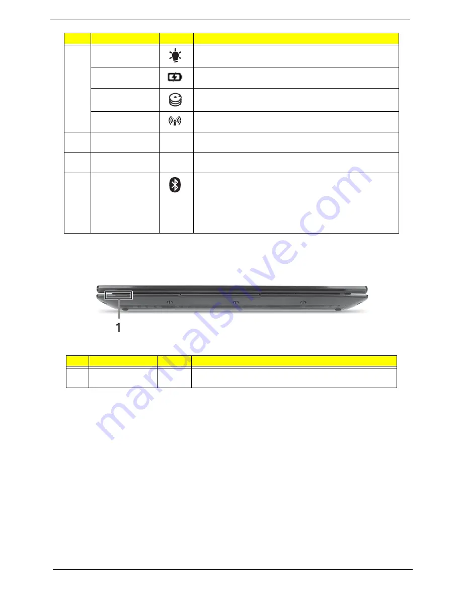
Acer ASPIRE 533 Скачать руководство пользователя страница 18

8

Chapter 1

Front View

6

Power indicator

Indicates the computer's power status.

Battery indicator

Indicates the computer's battery status.

HDD indicator

Indicates when the hard disk drive is active.

Wireless/3G 
indicator

Indicates when the 

7

Click buttons (left, 
and right)

The left and right buttons function like the left and right mouse 
buttons.

8

Touchpad

Touch-sensitive pointing device which functions like a 
computer mouse.

9

Bluetooth 
communication 
indicator 3G/
Wireless LAN 
communication 
indicator

Indicates the status of the Bluetooth communication.

(only for certain models)

Blue light on — 3G on / WiFi on or off

Orange light on — 3G off / WiFi on

Not lit — 3G off / WiFi off

#

Component

Icon

Description

1

Status Indicators

Light-Emitting Diodes (LED) that light up to show the status of 
the computer's functions and components.

No.

Component

Icon

Description

Содержание ASPIRE 533

Страница 1: ...Acer Aspire One 533 Series Service Guide PRINTED IN TAIWAN Service guide files and updates are available on the ACER CSD web for more information please refer to http csd acer com tw ...

Страница 2: ...II Revision History Please refer to the table below for the updates made to this service guide Date Chapter Updates ...

Страница 3: ...r expressed or implied with respect to the contents hereof and specifically disclaims any warranties of merchantability or fitness for any particular purpose Any Acer Incorporated software described in this manual is sold or licensed as is Should the programs prove defective following their purchase the buyer and not Acer Incorporated its distributor or its dealer assumes the entire cost of all ne...

Страница 4: ...N MESSAGES Denotes actual messages that appear on screen NOTE Gives bits and pieces of additional information related to the current topic WARNING Alerts you to any damage that might result from doing or not doing specific actions CAUTION Gives precautionary measures to avoid possible hardware or software problems IMPORTANT Reminds you to do specific actions relevant to the accomplishment of proce...

Страница 5: ... NOT be covered in this generic service guide In such cases please contact your regional offices or the responsible personnel channel to provide you with further technical details 2 Please note WHEN ORDERING FRU PARTS that you should check the most up to date information available on your regional web or channel If for whatever reason a part number change is made it will not be noted in the printe...

Страница 6: ...VI ...

Страница 7: ...ord Utilities 37 Miscellaneous Utilities 39 Machine Disassembly and Replacement 43 Disassembly Requirements 43 General Information 44 Pre disassembly Instructions 44 Disassembly Process 44 External Module Disassembly Process 45 External Modules Disassembly Flowchart 45 Removing the Battery Pack 46 Removing the SD Dummy Card 47 Removing the 3G Card 48 Removing the Keyboard 49 Removing the Lower Cov...

Страница 8: ...Replacing the RTC Battery 102 Replacing the Bluetooth Module 102 Replacing the LED Board 103 Replace the Button Board 104 Replacing the Upper Cover 106 External Module Assembly Process 109 Replacing the WLAN Module 109 Replacing the 3G Module 110 Replacing the HDD Module 111 Replacing the DIMM Module 114 Removing the Lower Cover 114 Replacing the Keyboard 115 Replacing the 3G Card 116 Replacing th...

Страница 9: ...nd Connector Locations 139 Mainboard Bottom View 140 Clearing Password Check and BIOS Recovery 141 Clearing Password Check 141 BIOS Recovery by Crisis Disk 142 FRU Field Replaceable Unit List 143 Exploded Diagrams 143 Main Assembly 143 LCD Assembly 144 Aspire one FRU List 146 Screw List 146 147 Model Definition and Configuration 148 Aspire Onel 148 Test Compatible Components 193 Online Support Inf...

Страница 10: ...X Table of Contents ...

Страница 11: ...25 kg 2 76 lbs for models with 6 cell battery pack Color options Glossy Black Glossy Red Glossy White CPU and chipset Intel Atom processor N455 N475 512 KB L2 cache 1 66 1 83 GHz 667 MHz FSB Mobile Intel NM10 Express Chipset Memory Single channel DDR3 SDRAM support with one soDIMM module Up to 1 GB of DDR3 system memory for Windows 7 Starter for small notebook PCs Up to 2 GB of DDR3 system memory ...

Страница 12: ...emory Stick PRO Duo Audio High definition audio support Two built in stereo speakers MS Sound compatible Built in digital microphone Webcam Acer Video Conference featuring Acer Crystal Eye webcam with 1280 x 1024 resolution Acer Crystal Eye webcam with 640 x 480 resolution Acer Video Conference Manager software featuring Video Quality Enhancement VQE technology supporting 640 x 480 resolution onli...

Страница 13: ...urs 63 W 5600 mAh 6 cell Li ion battery pack Battery life 10 hours ENERGY STAR Input and control Keyboard 84 85 88 key Acer FineTip keyboard 93 of full size smooth typing keyboard with international language support Touchpad Multi gesture touchpad supporting two finger scroll pinch rotate flip Input and output Multi in 1 card reader SD MMC MS MS PRO xD Three USB 2 0 ports External display VGA port...

Страница 14: ...net Security Suite Trial MyWinLocker except China Hong Kong Gaming Oberon GameZone except US Canada China Hong Kong Korea WildTangent US Canada only Communication and ISP Acer Crystal Eye Acer Video Conference Manager Microsoft Silverlight Skype Windows Live Essentials Wave 3 2 Mail Photo Gallery Live Messenger Movie Maker Writer Web links and utilities Acer Accessory Store Belgium France Germany ...

Страница 15: ... Protective bag Optional 1 GB 2 GB DDR3 1066 MHz DDR3DDR3667 MHz soDIMM module 6 cell Li ion battery pack 2 pin 40 W Acer MiniGo AC adapter External USB HDD External USB optical disc drive Warranty One year International Travelers Warranty ITW ...

Страница 16: ...m Tigerpoint Thermal Sensor ENE KBC KB926 AMP INT Speaker 10 100 Ethernet AR8152 Card Reader ENE6252 MINI Card x1 3G PCI Express EMC1402 LCD Conn LVDS SPI INT MIC HeadPhone MIC Jack RGB USB Port X2 R RJ45 SD MMC MS CONN DC DC Interface 3VALW 5VALW 1 5VP VCCP 0 89VP 1 8VP 0 75VS CPU_CORE Clock Generator CK505 USB BlueTooth CMOS CAM HDA CHARGER DC IN BATT IN SATA HDD GEN1 PCBGA360 USB Port x1 L To I...

Страница 17: ... communication configuration may vary by model 2 Microphone Internal microphone for sound recording 3 Display screen Also called Liquid Crystal Display LCD displays computer output 4 Power button indicator Indicates when the computer is turned on 5 Keyboard Provides all the features of a full sized computer keyboard ...

Страница 18: ... right mouse buttons 8 Touchpad Touch sensitive pointing device which functions like a computer mouse 9 Bluetooth communication indicator 3G Wireless LAN communication indicator Indicates the status of the Bluetooth communication only for certain models Blue light on 3G on WiFi on or off Orange light on 3G off WiFi on Not lit 3G off WiFi off Component Icon Description 1 Status Indicators Light Emi...

Страница 19: ...SD MultiMediaCard MMC Memory Stick MS Memory Stick PRO MS PRO xD Picture Card xD Note Push to remove install the card Only one card can operate at any given time 2 Headphone speaker line out jack Connects to line out audio devices e g speakers headphones Microphone in jack Accepts inputs from external microphones 3 USB 2 0 port Connects to USB 2 0 devices e g USB mouse 4 Kensington lock slot Conne...

Страница 20: ...e model purchased 2 3G SIM card slot Accepts a 3G SIM card for 3G connectivity only for certain models 3 Battery release latch Releases the battery for removal 4 Battery lock Locks the battery in position 5 Ventilation slots and or cooling fan Enables the computer to stay cool even after prolonged use Note Do not cover or obstruct the opening of the fan 6 Speaker Emits audio from your computer 1 6...

Страница 21: ...d keep it and your fingers dry and clean The TouchPad is sensitive to finger movement hence the lighter the touch the better the response Tapping too hard will not increase the TouchPad s responsiveness Function Left Button 2 Right Button 3 Main TouchPad 1 Execute Quickly click twice Tap twice at the same speed as double clicking a mouse button Select Click once Tap once Drag Click and hold then u...

Страница 22: ...aps Lock When Caps Lock is on all alphabetic characters typed are in uppercase Num Lock Fn F11 When Num Lock is on the embedded keypad is in numeric mode The keys function as a calculator complete with the arithmetic operators and Use this mode when you need to do a lot of numeric data entry A better solution would be to connect an external keypad Scroll Lock Fn F12 When Scroll Lock is on the scre...

Страница 23: ...work domain M Minimizes all windows R Open the Run dialog box T Cycle through programs on the taskbar U Open Ease of Access Center X Open Windows Mobility Center BREAK Display the System Properties dialog box SHIFT M Restore minimized windows to the desktop TAB Cycle through programs on the taskbar by using Windows Flip 3 D SPACEBAR Bring all gadgets to the front and select Windows Sidebar CTRL F ...

Страница 24: ...F4 Sleep Puts the computer in Sleep mode Fn F5 Display toggle Switches display output between the display screen external monitor if connected and both Fn F6 Screen blank Turns the display screen backlight off to save power Press any key to return Fn F7 TouchPad toggle Turns the internal TouchPad on and off Fn F8 Speaker toggle Turns the speakers on and off Fn Brightness up Increases the screen br...

Страница 25: ... a text editor or word processor 2 Hold Alt Gr and then press the 5 key at the upper center of the keyboard NOTE Some fonts and software do not support the Euro symbol The US dollar sign 1 Open a text editor or word processor 2 Hold Shift and then press the 4 key at the upper center of the keyboard NOTE This function varies according to the language settings ...

Страница 26: ...00 LAN ENE UB6252 card reader support MS MS Pro SD MMC xD Item CPU Speed Cores Bus Speed Mfg Tech Cache Size Package Core Voltage Acer P N N450 1 66 GHz 1 667 MHz 45 nm 512 KB Micro FCBGA8 0 9V 1 100V KC ANB01 450 N455 1 66 GHz 1 667 MHz 45 nm 512 KB Micro FCBGA8 0 9V 1 100V CPU Temperature Fan Speed RPM SPL Spec dBA 47 4700 26 50 5200 29 55 5500 31 95 5500 31 Item Specification Memory controller ...

Страница 27: ...t Win Flash Wake on LAN from S3 Wake on LAN from S4 in AC mode System information Item Specification LAN Chipset Atheros AR8114 AR8132 LAN connector type LAN connector location Features Supports 10 100 Item Specification Vendor Model Name Seagate ST9160310AS Seagate ST9250827AS Seagate ST9250315AS HGST L9A300 HTS543225 HTS543216 WD WD2500BEVT WD1600BEVT Capacity GB 160 250 250 250 160 250 160 Byte...

Страница 28: ...sec max 400 794 typical 395 952 typical Media data transfer rate Gbytes sec max 3 3 DC Power Requirements Voltage tolerance 5V 5 5V 5 Item Specification Chipset Data throughput Protocol 3 0 HS Interface Connector type Item Specification Vendor model name Samsung LTN101AT01 A01 AUO B101EW02 AUO B101AW03 V0 CMO N101L6 L02 CMO N101L6 L0B Samsung LTN101NT02 A04 LG LP101WSA TLA1 LG LP101WSA TLN1 INNOLU...

Страница 29: ...Right CR 10 Left Vertical Upper CR 10 Lower 45 45 20 45 Item Specification Vendor model name Brightness conditions Input voltage v Input current mA Output voltage V RMS Output current mA RMS Output voltage frequency KHz Resolution 24 bits 30 bits 36 bits 48 bits 640x480p 60Hz 4 3 720x480p 60Hz 4 3 720x480p 60Hz 16 9 1280x720p 60Hz 16 9 1920x1080i 60Hz 16 9 1440x480i 60Hz 4 3 1440x480i 60Hz 16 9 19...

Страница 30: ...keys Phantom key auto detect Overlay numeric keypad Support independent pgdn pgup pgup home end keys Support reverse T cursor keys Factory configurable different languages by OEM customer Item Specification Vendor and model Suyin Camera Rosa Liteon Camera Lily Type 0 3M LDV Item Specification Features 3G card in mini PCI card size Control by USB interface User accessible SIM card by battery remove...

Страница 31: ...pins pin sharing with digital microphone interface Supports EAPD External Amplifier Power Down control for external amplifier Supports anti pop mode when analog power AVDD is on and digital power is off Supports 1 5V 3 3V scalable I O for HD Audio link 48 pin LQFP Green package Item Specification Type Foxconn Wirelss LAN Broadcom 4313 Features Acer InviLink Nplify 802 11b g n Wi Fi CERTIFIED Acer ...

Страница 32: ...wo on the right side Item Specification Compliance level Thoroughput Number of HDMI port s Location Item Specification PCMCIA controller Supports card type Number of slots Access location Supports ZV Zoomed Video port Supports 32 bit CardBus Item Specification Core logic Tiger Point Chipset VGA LAN Atheros AR8132 USB 2 0 Super I O controller Bluetooth Foxconn Bluetooth BRM 2070 Wireless Foxconn Wi...

Страница 33: ...ned off completely Working G0 S0 Individual devices such as the CPU and hard disc may be power managed in this state Suspend to RAM S3 CPU set power down VGA Suspend PCMCIA Suspend Audio Power Down Hard Disk Power Down CD ROM Power Down Super I O Low Power mode Save to Disk S4 Also called Hibernation Mode System saves all system states and data onto the disc prior to power off the whole system Ite...

Страница 34: ... 7 Suspend to ON state The system will go into ON state when the power button is pressed 8 Hibernate to ON state The system will go into ON state when the power button is pressed 9 Soft Off to ON state The system will go into ON state when the power button is pressed Item Specification Lock Indicates lock status for Caps lock and Num lock System state Green color and blue color solid on System on ...

Страница 35: ...er multi boot menu In this menu user can change boot device without entering BIOS SETUP Utility Navigating the BIOS Utility There are six menu options Information Main Security Boot and Exit Follow these instructions To choose a menu use the left and right arrow keys To choose an item use the up and down arrow keys To change the value of a parameter press F5 or F6 Press Esc while you are in any of...

Страница 36: ...is field shows product name of the system Manufacturer Name This field displays the manufacturer of this system UUID Universally Unique Identifier UUID is an identifier standard used in software construction standardized by the Open Software Foundation OSF as part of the Distributed Computing Environment DCE InsydeH20 Setup Utility Rev 3 5 F1 ESC Help Exit Select Item Select Menu Change Va lues Se...

Страница 37: ...boot from LAN remote server Option Enabled or Disabled F12 Boot Menu Enables disables Boot Menu during POST Option Enabled or Disabled D2D Recovery Enables disables D2D Recovery function The function allows the user to create a hidden partition on hard disc drive to store operation system and restore the system to factory defaults Option Enabled or Disabled SATA Mode Control the mode in which the ...

Страница 38: ...Set User Password Press Enter to set the user password When user password is set this password protects the BIOS Setup Utility from unauthorized access The user can enter Setup menu only and does not have right to change the value of parameters Set IDE0 Hdd Password Enter to set the HDD password Power on password Defines whether a password is required or not while the events defined in this group ...

Страница 39: ...ter to Set 4 If desired you can opt to enable the Password on boot parameter 5 When you are done press F10 to save the changes and exit the BIOS Setup Utility Removing a Password Follow these steps 1 Use the and keys to highlight the Set Supervisor Password parameter and press the Enter key The Set Password box appears 2 Type the current password in the Enter Current Password field and press Enter...

Страница 40: ... When you are done press F10 to save the changes and exit the BIOS Setup Utility If the verification is OK the screen will display as following The password setting is complete after the user presses Enter If the current password entered does not match the actual current password the screen will show you the Setup Warning If the new password and confirm new password strings do not match the screen...

Страница 41: ...e then press F5 to move it down the list or F6 to move it up the list Press Esc to escape the menu F1 ESC Help Exit Select Item Select Menu Change Va lues Select SubMenu Enter F9 F10 Setup Default Save and Exit Boot priority order 1 IDE0 ST9 2 IDE1 3 USB FDD 4 5 USB HDD 6 USB CDROM Boot priority order 1 IDE0 ST9250315AS 2 IDE1 3 USB FDD 4 Network Boot Atheros Boot Agent 5 USB HDD 6 USB CDROM F5 F6...

Страница 42: ...ues for all SETUP item Discard Changes Load previous values from CMOS for all SETUP items Save Changes Save Setup Data to CMOS Item Specific Help Exit System Setup and save your changes to CMOS F1 ESC Help Exit Select Item Select Menu Change Values Select SubMenu Enter F9 F10 Setup Default Save and Exit Exit Saving Changes Exit Discarding Changes Load Setup Defaults Discard Changes Save Changes Ex...

Страница 43: ...y Diskette before you use the flash utility NOTE Do not install memory related drivers XMS EMS DPMI when you use the flash NOTE Please use the AC adaptor power supply when you run the flash utility If the battery pack does not contain enough power to finish BIOS flash you may not boot the system because the BIOS is not completely loaded Fellow the steps below to run the flash 1 Prepare a bootable ...

Страница 44: ... begins as shown Item Specific Help Use or to select a device then press F5 to move it down the list or F6 to move it up the list Press Esc to escape the menu F1 ESC Help Exit Select Item Select Menu Change Va lues Select SubMenu Enter F9 F10 Setup Default Save and Exit Boot priority order 1 IDE0 ST9 2 IDE1 3 USB FDD 4 5 USB HDD 6 USB CDROM Boot priority order 1 IDE0 ST9250315AS 2 IDE1 3 USB FDD 4...

Страница 45: ...he message Please do not remove AC Power Source displays NOTE If the AC power is not connected the following message displays Plug in the AC power to continue 5 Flash is complete when the message Flash programming complete displays ...

Страница 46: ...rm the following steps to use the WinFlash Utility 1 Double click the WinFlash executable 2 Click OK to begin the update A progress screen displays 3 When the process is complete close all programs and applications and reboot the system ...

Страница 47: ... error is displayed select the Enter Unlock Password option on the screen 2 An Encode key is generated for unlocking utilities Note down this key 3 Execute the UnlockHD EXE file to create the unlock code in DOS Mode using the format UnlockHD Encode key with the code noted in the previous step as follows UnlockHD 76943488 4 The command generates a password which can be used for unlocking the HDD Pa...

Страница 48: ...strument to short the J14 jumper as shown below Cleaning BIOS Passwords To clean the User or Supervisor passwords perform the following steps 1 From a DOS prompt execute clnpwd exe 2 Press 1 or 2 to clean the desired password shown on the screen The onscreen message determines whether the function is successful or not ...

Страница 49: ...m to be used in the DMI pool for hardware management When the BIOS displays Verifying DMI pool data it is checking the table correlates with the hardware before sending to the operating system Windows etc To update the DMI Pool perform the following steps 1 Enter into DOS 2 Execute dmitools exe The following messages show dmitools usage DMITOOLS R WP WS WU STRING dmitools r Read dmi string from bi...

Страница 50: ...EPROM Input dmitools wp Acer Example 3 Write Serial Number to EEPROM Input dmitools ws 01234567890123456789 Example 4 Write UUID to EEPROM Create UUID from Intel WFM20 pdf Input dmitools wu Example 5 Write Asset Tag to EEPROM Input dmitools wa Acer Asstag Using the LAN MAC Utility Perform the following steps to write MAC information to eeprom 1 Use a text editor for example Notepad to edit the MAC...

Страница 51: ...Chapter 2 41 3 Execute MAC BAT to write MAC information to eeprom ...

Страница 52: ...42 Chapter 2 ...

Страница 53: ...ooting Disassembly Requirements To disassemble the computer you need the following tools Wrist grounding strap and conductive mat for preventing electrostatic discharge Flat screwdriver Philips screwdriver Plastic flat screwdriver Plastic tweezers NOTE The screws for the different components vary in size During the disassembly process group the screws with the corresponding components to avoid mis...

Страница 54: ...assembly Process The disassembly process is divided into the following stages External module disassembly Main unit disassembly LCD module disassembly The flowcharts provided in the succeeding disassembly sections illustrate the entire disassembly sequence Observe the order of the sequence to avoid damage to any of the hardware components For example if you want to remove the mainboard you must fi...

Страница 55: ... Flowchart The flowchart below gives you a graphic representation on the entire disassembly sequence and instructs you on the components that need to be removed during servicing For example if you want to remove the main board you must first remove the keyboard then disassemble the inside assembly frame in that order Screw List Step Screw Quantity Part No ...

Страница 56: ...irection shown 2 Slide and hold the battery release latch to the release position 1 then lift out the battery pack from the main unit 2 NOTE The battery has been highlighted with a yellow oval as shown in the above image Please detach the battery and follow local regulations for disposal 1 2 ...

Страница 57: ...Chapter 3 47 Removing the SD Dummy Card 1 Push the SD dummy card inwards to eject it 2 Pull the card out from the slot ...

Страница 58: ...48 Chapter 3 Removing the 3G Card 1 See Removing the Battery Pack on page 46 2 Push the 3G card inwards to eject it 3 Pull the card out from the slot ...

Страница 59: ...oving the Keyboard 1 See Removing the Battery Pack on page 46 2 Push down on the three 3 latches holding the top center of the keyboard 3 Pry up the keyboard at the top center 4 Turn the keyboard over onto the palmrest ...

Страница 60: ...50 Chapter 3 5 Unlock the FPC 6 Remove the FPC and the keyboard ...

Страница 61: ...e 49 2 Remove the two 2 screws from the upper cover as shown 3 Using a screwdriver or other straight tool push through the hole in the upper cover to release the lower cover 4 Turn the computer over and remove the lower cover Step Size Quantity Screw Type Lower Door M2 6 2 ...

Страница 62: ...52 Chapter 3 Removing the DIMM Module 1 See Removing the Lower Cover on page 51 2 Push out the release latches on both sides of the DIMM socket to release the DIMM module 3 Remove the DIMM module ...

Страница 63: ...e Removing the Lower Cover on page 51 2 Remove the one 1 screw NOTE The HDD carrier purchased may differ from the model shown 3 Move the HDD away from the connector in the direction shown Step Size Quantity Screw Type HDD Module M2 6 1 M2 4 3 ...

Страница 64: ...ove the HDD module 5 Remove the four 4 screws two each side securing the hard disk to the carrier NOTE Remove screws in order from 1 to 4 6 Remove the HDD from the carrier Step Size Quantity Screw Type HDD Carrier M3 3 4 ...

Страница 65: ...r Cover on page 51 2 Remove the adhesive tape securing the antenna cables 3 Disconnect the antenna cables from the 3G module NOTE Cable placement is YELLOW to the MAIN terminal closest to the HDD and BLUE to the AUX terminal closest to the edge of the computer ...

Страница 66: ...e antennas away and remove the one 1 screw 5 Remove the 3G module from the 3G socket NOTE When removing the 3G module the WLAN antenna cables may be removed to simplify removal Step Size Quantity Screw Type 3G Module M2 3 1 ...

Страница 67: ...sconnect the antenna cables from the WLAN module NOTE Cable placement is BLACK to the MAIN terminal closest to the HDD and WHITE to the AUX terminal closest to the edge of the computer 3 Move the antennas away and remove the one 1 screw Step Size Quantity Screw Type WLAN Module M2 3 1 ...

Страница 68: ...58 Chapter 3 4 Remove the WLAN module from the WLAN socket NOTE When removing the WLAN module the 3G antenna cables may be removed to simplify removal ...

Страница 69: ...Chapter 3 59 Main Unit Disassembly Process Main Unit Disassembly Flowchart Screw List Step Screw Quantity Part No ...

Страница 70: ...60 Chapter 3 Removing the Upper Cover 1 Unlock and disconnect the LED board FFC 2 Unlock and disconnect the Touchpad FFC ...

Страница 71: ...a grounding wire attached to the LVDS wire Ensure it is reattached during reassembly process 4 Remove the eleven 11 screws in the lower cover Step Size Quantity Screw Type Upper Cover M2 6 5 Step Size Quantity Screw Type Lower Cover M2 6 red call out 4 M2 3 green call out 2 M2 4 purple call out 5 ...

Страница 72: ...sis 6 Continue along the front and left side until the upper cover is completely seperated from the chassis 7 There are latches in the hinge area that will not be released with steps 5 and 6 above When removing the upper cover pull from the back of the upper cover next to the hinges to unlock the latches 8 Remove the upper cover ...

Страница 73: ...1 See Removing the Upper Cover on page 60 2 Locate the button board on the upper cover 3 Remove the yellow tape securing the button board FFC 4 Release the button board FFC locking latch and disconnect the button board FFC from the connector ...

Страница 74: ...ull the button board FFC off the adhesive 6 Remove the two 2 screws securing the button board bracket to the upper cover 7 Remove the button board from the upper cover Step Size Quantity Screw Type Button Board M2 3 2 ...

Страница 75: ...ing the LED Board 1 See Removing the Upper Cover on page 60 2 Remove the tape covering the LED board FFC 3 Remove the one 1 screw 4 Lift the LED board away from the chassis Step Size Quantity Screw Type LED Board M2 3 1 ...

Страница 76: ...ng the Bluetooth Module 1 See Removing the Upper Cover on page 60 2 Disconnect the Bluetooth cable from the mainboard connector 3 Lift the Bluetooth module off the adhesive 4 Disconnect the cable from the Bluetooth module ...

Страница 77: ...place Break the solder and remove the RTC battery NOTE The battery has been highlighted with a yellow oval as shown in the above image Please detach the battery and follow local regulations for disposal Removing the Mainboard 1 See Removing the Upper Cover on page 60 2 Remove the tape covering LVDS grounding wire ...

Страница 78: ...68 Chapter 3 3 Peel back the LVDS grounding wire from the 3G card casing NOTE CCD and microphone cables are bundled with the LVDS cable 4 Disconnect the LVDS cable 5 Disconnect the DC In cable ...

Страница 79: ...Chapter 3 69 6 Remove the adhesive tape securing the speaker cable 7 Disconnect the speaker cable 8 Remove the two 2 screws Step Size Quantity Screw Type Mainboard M2 3 2 ...

Страница 80: ...apter 3 9 Lift up the center of the mainboard to release it from the chassis 10 Tilt the mainboard to 45 degrees 1 to ensure the IO ports can be removed from the chassis and lift the mainboard away 2 1 2 1 2 ...

Страница 81: ...rmal Module 1 See Removing the Mainboard on page 67 2 Disconnect the fan cable 3 Remove the three 3 screws 1 to 3 in numerical order 4 Remove the thermal module from the mainboard Step Size Quantity Screw Type Thermal module M2 3 3 ...

Страница 82: ...72 Chapter 3 NOTE Circuit boards 10 cm have been highlighted with a yellow rectangle as shown in the previous image Please detach the Circuit board and follow local regulations for disposal ...

Страница 83: ...oving the LCD Module 1 See Removing the Mainboard on page 67 2 Lift the DC in cable out of the chassis 3 Remove the DC In jack from the chassis 4 Remove the left antenna cables from the cable guides on the bottom cover ...

Страница 84: ...74 Chapter 3 5 Remove the four 4 screws 6 Remove the LCD module from the chassis Step Size Quantity Screw Type LCD Module M2 4 4 ...

Страница 85: ...r Module 1 See Removing the Mainboard on page 67 2 Remove the tape covering speaker wire 3 Remove the four 4 screws 4 Remove the cables from the retention guides and pull the speakers away Step Size Quantity Screw Type Speakers M2 3 4 ...

Страница 86: ...76 Chapter 3 LCD Module Disassembly Process LCD Module Disassembly Flowchart Screw List Step Screw Quantity Part No ...

Страница 87: ...ule on page 73 2 Remove the two 2 screw caps and two 2 screws 3 Starting from the bottom center of the bezel pry the bezel upwards and away from the panel Move along the edge until the bezel is completely removed I Step Size Quantity Screw Type LCD Bezel M2 4 Ni 2 ...

Страница 88: ...78 Chapter 3 Removing the Camera Module 1 See Removing the LCD Bezel on page 77 2 Lift the camera from the LCD module 3 Disconnect the camera cable and remove the camera ...

Страница 89: ...fferent from model purchased 1 See Removing the Camera Module on page 78 2 Remove the four 4 securing screws from the LCD Panel NOTE Remove cables from hinges before removing screws 3 Unwrap and separate the LVDS cable from the left hinge Step Size Quantity Screw Type LCD Panel M2 3 4 ...

Страница 90: ...80 Chapter 3 4 Unwrap and separate the antenna cables from the right hinge 5 Remove the adhesive foil from the microphone module ...

Страница 91: ...Chapter 3 81 6 Lift the microphone out of its socket 7 Lift up the adhesive foil tabs that attach the LVDS cable and antennas to the panel ...

Страница 92: ...82 Chapter 3 8 Lift the LCD Panel out of the module 9 Turn the LCD panel over and place it face down on a clean surface 10 Remove the camera cable from the back of the LCD panel ...

Страница 93: ...Chapter 3 83 11 Peel up the transparent adhesive protector 12 Disconnect the LVDS cable from the panel connector ...

Страница 94: ...emoving the LCD Brackets 1 See Removing the LCD Panel on page 79 2 Remove the four 4 screws from the LCD brackets 3 Lift the brackets away from the upper cover Step Size Quantity Screw Type LCD Panel Brackets M2 3 4 ...

Страница 95: ...LAN Antennas 3G is only in some models 1 See Removing the LCD Brackets on page 84 2 Lift the adhesive foam padding off the adhesive foil 3 Remove the adhesive foil tabs from the antenna cable 4 Remove the cable from the retention guides ...

Страница 96: ... the left auxilliary WLAN antenna off the LCD module cover and remove 6 Lift the left auxilliary 3G antenna adhesive foil off the LCD cover and remove the antenna 7 Repeat steps 5 and 6 for the right 3G and WLAN antennas ...

Страница 97: ...G and WLAN Antennas NOTE 3G is only available in some models 1 Replace the left auxilliary 3G antenna and reapply the adhesive foil to the LCD cover 2 Replace the left auxilliary WLAN antenna to the LCD module cover 3 Replace the cable in the retention guides ...

Страница 98: ...88 Chapter 3 4 Replace the adhesive foil tabs for the antenna cable 5 Reapply the adhesive foam padding to the adhesive foil Replacing the LCD Brackets 1 Place the brackets onto the upper cover ...

Страница 99: ... the LCD brackets Replacing the LCD Panel 1 Place the LCD panel face down on a clean surface 2 Reconnect the LVDS cable to the panel connector 3 Reattach the transparent adhesive protector Step Size Quantity Screw Type LCD Panel Brackets M2 3 4 ...

Страница 100: ...90 Chapter 3 4 Reattach the camera cable to the back of the LCD panel 5 Place the LCD Panel into the module 6 Replace the adhesive foil tabs that attach the LVDS cable and antennas to the panel ...

Страница 101: ...Chapter 3 91 7 Place the microphone into its socket 8 Replace the adhesive foil to the microphone module 9 Replace the antenna cables to the right hinge ...

Страница 102: ...ft hinge 11 Replace the four 4 securing screws from the LCD Panel NOTE Ensure the cables are installed properly before replacing the screws Replacing the Camera Module 1 Reconnect the CCD cable as shown Step Size Quantity Screw Type LCD Panel M2 3 4 ...

Страница 103: ...ver Replacing the LCD Bezel 1 Place the bezel hinge covers over the hinges Ensure the cables are correctly exiting the hinges 2 Press down on the top middle edge of the bezel to engage the locking clips 3 Move along the sides to the bottom of the LCD module until all latches under the bezel are locked ...

Страница 104: ...94 Chapter 3 4 Press the bezel downwards at the bottom of the LCD module until the latches are locked 5 Replace the two 2 screw caps and two 2 screws Step Size Quantity Screw Type LCD Bezel M2 4 Ni 2 ...

Страница 105: ...ain Unit Assembly Process Replacing the Speaker Module 1 Place the speakers on the lower cover and replace the cables in the retention guides 2 Replace the four 4 screws Step Size Quantity Screw Type Speakers M2 3 4 ...

Страница 106: ...96 Chapter 3 3 Replace the tape covering the speaker wire Replacing the LCD Module 1 Replace the LCD module on the chassis 2 Replace the four 4 screws Step Size Quantity Screw Type LCD Module M2 4 4 ...

Страница 107: ...Chapter 3 97 3 Replace the antenna cables in the cable guides on the bottom cover 4 Place the DC In jack into the chassis 5 Place the DC In cable in the chassis ...

Страница 108: ...98 Chapter 3 Replacing the Thermal Module 1 Place the thermal module on the mainboard 2 Replace the three 3 screws and tighten in numerical order 1 to 3 ...

Страница 109: ... Reconnect the fan cable Replacing the Mainboard 1 Place the mainboard in the lower cover left side first 2 1 Grasp the center of the mainboard and 2 gently press down on the edge of the chassis to lock in place 2 1 ...

Страница 110: ...100 Chapter 3 3 Replace the two 2 screws 4 Reconnect the speaker cable 5 Replace the adhesive tape securing the speaker cable Step Size Quantity Screw Type Mainboard M2 3 2 ...

Страница 111: ...Chapter 3 101 6 Reconnect the DC In cable 7 Reconnect the LVDS cable 8 Reattach the LVDS grounding wire to the 3G card casing NOTE CCD and microphone cables are bundled with the LVDS cable ...

Страница 112: ... 9 Reapply the tape covering LVDS grounding wire Replacing the RTC Battery 1 Place the RTC battery on the mainboard and resolder Replacing the Bluetooth Module 1 Reconnect the Bluetooth cable to the Bluetooth module ...

Страница 113: ...pter 3 103 2 Place the Bluetooth module onto the lower cover and press down to afix 3 Reconnect the Bluetooth cable to the mainboard connector Replacing the LED Board 1 Place the LED board onto the chassis ...

Страница 114: ...104 Chapter 3 2 Replace the one 1 screw 3 Replace the tape covering the LED board FFC Replace the Button Board 1 Place the button board on the upper cover Step Size Quantity Screw Type LED Board M2 3 1 ...

Страница 115: ...the two 2 screws securing the button board bracket to the upper cover 3 Reattach the button board FFC to the adhesive 4 Reconnect and lock the button board FFC to the connector Step Size Quantity Screw Type Button Board M2 3 2 ...

Страница 116: ...106 Chapter 3 5 Reattach the yellow tape securing the button board FFC Replacing the Upper Cover 1 Replace the upper cover 2 Press down at the specifried places to reattach the upper cover ...

Страница 117: ... remaining screws on the upper cover NOTE Upperleft screw has a grounding wire attached to the LVDS wire Ensure it is reattached during reassembly process Step Size Quantity Screw Type Lower Cover M2 6 red call out 4 M2 3 green call out 2 M2 4 purple call out 5 Step Size Quantity Screw Type Upper Cover M2 6 5 ...

Страница 118: ...108 Chapter 3 5 Reconnect and lock the touchpad FFC 6 Reconnect and lock the LED board FFC ...

Страница 119: ...Chapter 3 109 External Module Assembly Process Replacing the WLAN Module 1 Insert the WLAN module into the WLAN socket 2 Replace the one 1 screw Step Size Quantity Screw Type WLAN Module M2 3 1 ...

Страница 120: ... Cable placement is BLACK to the MAIN terminal closest to the HDD and WHITE to the AUX terminal closest to the edge of the computer Replacing the 3G Module 1 Insert the 3G module into the 3G socket 2 Replace the one 1 screw Step Size Quantity Screw Type 3G Module M2 3 1 ...

Страница 121: ...losest to the HDD and BLUE to the AUX terminal closest to the edge of the computer 4 Replace the adhesive tape securing the antenna cables Replacing the HDD Module 1 Insert the HDD into the carrier 2 Replace the four 4 screws two each side securing the hard disk to the carrier NOTE Remove screws in order from 1 to 4 ...

Страница 122: ...Insert the HDD module 4 Move the HDD toward the connector in the direction shown 5 Replace the one 1 screw NOTE The HDD carrier purchased may differ from the model shown Step Size Quantity Screw Type HDD Carrier M3 3 4 ...

Страница 123: ...Chapter 3 113 Step Size Quantity Screw Type HDD Module M2 6 1 M2 4 3 ...

Страница 124: ...114 Chapter 3 Replacing the DIMM Module 1 Insert the DIMM module into the DIMM socket and press to lock in place Removing the Lower Cover 1 Replace the lower cover as shown ...

Страница 125: ...Chapter 3 115 2 Replace the two 2 screws to the upper cover as shown Replacing the Keyboard 1 Reconnect the FPC to the keyboard 2 Lock the FPC Step Size Quantity Screw Type Lower Door M2 6 2 ...

Страница 126: ...Chapter 3 3 Turn the keyboard over onto the upper cover 4 Push down on the three 3 latches holding the top center of the keyboard Replacing the 3G Card 1 Push the card into the slot until it locks in place ...

Страница 127: ...nd push until the card clicks into place and is flush with the casing Replacing the Battery Pack 1 Slide and hold the battery release latch to the release position 1 then insert the battery pack into the main unit 2 2 Turn computer over Slide the battery lock in the direction shown 1 2 ...

Страница 128: ...118 Chapter 3 ...

Страница 129: ...ning the diagnostic test or by repeating the same operation 3 Use the following table with the verified symptom to determine which page to go to 4 If the Issue is still not resolved see Online Support Information on page 207 Symptoms Verified Go To Power On Issue Page 120 No Display Issue Page 121 LCD Failure Page 123 Internal Keyboard Failure Page 123 TouchPad Failure Page 124 Internal Speaker Fa...

Страница 130: ...Remove any surge protectors between the computer and the electrical outlet Plug the computer directly into a known good electrical outlet 4 Disconnect the power and open the casing to check the Thermal Unit see Thermal Unit Failure on page 129 and fan airways are free of obstructions 5 Remove all external and non essential hardware connected to the computer that are not necessary to boot the compu...

Страница 131: ...tton for 10 seconds Reconnect the power and reboot the computer 4 Connect an external monitor to the computer and switch between the internal display and the external display is by pressing Fn F5 on this model If the POST or video appears on the external display see LCD Failure on page 123 5 Disconnect power and all external devices including port replicators or docking stations Remove any memory ...

Страница 132: ...Click and drag the Resolution slider to the desired resolution e Click Apply and check the display Readjust if necessary 6 Roll back the video driver to the previous version if updated 7 Remove and reinstall the video driver 8 Check the Device Manager to determine that The device is properly installed There are no red Xs or yellow exclamation marks There are no device conflicts No hardware is list...

Страница 133: ...efective FRUs Built In Keyboard Failure If the built in Keyboard fails perform the following actions one at a time to correct the problem Do not replace a non defective FRUs Start Check LCD module Swap LCD cable LCD panel OK NG Swap M B START Keyboard FPC well connected No Connect it well Keyboard OK No Replace keyboard Replace M B ...

Страница 134: ...If the internal Speakers fail perform the following actions one at a time to correct the problem Do not replace a non defective FRUs Start Check M B T P FFC Re assemble the T P FFC to M B OK NG Check Logic Upper OK Swap Re assemble the T P board or T P FFC OK NG Swap M B Start Check M B SPK cable Re assemble the SPK cable to M B OK NG Check Logic Lower OK Swap Logic lower OK NG Swap M B ...

Страница 135: ...ag the slider to 50 Ensure that the volume is not muted b Click Mixer to verify that other audio applications are set to 50 and not muted 6 Navigate to Start Control Panel Hardware and Sound Sound Ensure that Speakers are selected as the default audio device green check mark NOTE If Speakers does not show right click on the Playback tab and select Show Disabled Devices clear by default 7 Select Sp...

Страница 136: ...ct Show Disabled Devices clear by default 3 The microphone appears on the Recording tab 4 Right click on the microphone and select Enable 5 Select the microphone then click Properties Select the Levels tab 6 Increase the volume to the maximum setting and click OK 7 Test the microphone hardware a Select the microphone and click Configure b Select Set up microphone c Select the microphone type from ...

Страница 137: ...and resolve issues with the computer i When complete click Finish If an issue is discovered follow the onscreen information to resolve the problem 4 Run the Windows Memory Diagnostic Tool For more information see Windows Help and Support 5 Restart the computer and press F2 to enter the BIOS Utility Check the BIOS settings are correct and that CD DVD drive is set as the first boot device on the Boo...

Страница 138: ...AN fails perform the following actions one at a time to correct the problem Do not replace a non defective FRUs Start Check IO B to M B CONN Re assemble the IO B CONN to M B OK NG Check IO B OK Swap IO B OK NG Swap M B Start Check WL antenna to WL card Re assemble the antenna to WL card OK NG Check antenna OK Swap The antenna OK NG Swap M B Check WL card OK Swap the WL card OK NG ...

Страница 139: ... Remove any recently added hardware and associated software 7 Remove any recently added software and reboot 8 Restore system and file settings from a known good date using System Restore If the issue is not fixed repeat the preceding steps and select an earlier time and date 9 Run the Event Viewer to check the events log for errors For more information see Windows Help and Support 10 Roll back the...

Страница 140: ...Other Failures If the CRT Switch Dock LAN Port external MIC or Speakers PCI Express Card 5 in 1 Card Reader or Volume Wheel fail perform the following general steps to correct the problem Do not replace a non defective FRUs 1 Check Drive whether is OK 2 Check Test Fixture is ok 3 Swap M B to Try ...

Страница 141: ...her a short circuit is suspected or whether the system is inoperative Follow these procedures to isolate the failing FRU do not isolate non defective FRU NOTE Verify that all attached devices are supported by the computer NOTE Verify that the power supply being used at the time of the failure is operating correctly See Power On Issue on page 120 1 Power off the computer 2 Visually check them for d...

Страница 142: ...0x07 Verify all DIMMs are x8 or x16 width 0x08 Find a common CAS latency between the DIMMS and the MCH 0x09 Determine the memory frequency and CAS latency to program 0x10 Determine the smallest common TRAS for all DIMMs 0x11 Determine the smallest common TRP for all DIMMs 0x12 Determine the smallest common TRCD for all DIMMs 0x13 Determine the smallest refresh period for all DIMMs 0x14 Verify burs...

Страница 143: ...in at the stage1 0x27 Report every memory range do the hard ware ECC init 0x28 Report status code of every memory range 0x50 Get the root bridge handle 0x51 Notify pci bus driver starts to program the resource 0x58 Reset the host controller 0x5A IdeBus begin initialization 0x79 Report that the remote terminal is being disabled 0x7A Report that the remote terminal is being enabled 0x90 Keyboard res...

Страница 144: ... 0xAA PEI_PLATFORM_STAGE2 0xAC PEI_SB_SMBUS_ARP_DISABLED 0x0F PEI_HOST_TO_SYSTEM 0x40 PEI_MEMORY_INIT 0x41 PEI_S3_RESUME 0xAD PEI_CLOCK_GEN 0xAB PEI_OP_PRESENCE 0xAE PEI_FIND_FV 0x16 PEI_H2O_DEBUG_IO 0x17 PEI_H2O_DEBUG_COMM 0x16 0x1F PEI_RESERVED 0x20 0x2E PEI_OEM_DEFINED 0xAF PEI_DXE_IPL Code Description 0x30 RESERVED 0xB6 DXE_CRC32_SECTION_EXTRACT 0xB8 SCRIPT_SAVE 0xB9 ACPI_S3_SAVE 0xBA SMART_TI...

Страница 145: ...A_BUS 0xE9 ISA_SERIAL 0xED BUS_PCI_UNDI 0xEC PCI_BUS 0xF6 BOOT_PRIORITY 0xF7 FVB_SERVICE 0xF8 ACPI_PLATFORM 0xFB PCI_HOT_PLUG 0xFC DXE_PLATFORM 0xFD PLATFORM_IDE 0x97 SMBIOS 0x98 MEMORY_SUB_CLASS 0x99 MISC_SUB_CLASS 0x82 CON_PLATFORM 0x83 SAVE_MEMORY_CONFIG 0x84 ACPI_SUPPORT 0x85 CON_SPLITTER_UGA_VGA CON_SPLITTER 0x88 VGA_CLASS 0x89 DATA_HUB 0x60 DISK_IO 0x8B MEMORY_TEST 0x62 CRISIS_RECOVERY 0x8D ...

Страница 146: ...ENCH 0x9E HII_DATABASE 0x9F OEM_SETUP_BROWSER 0x8C OEM_BADGING_SUPPORT 0xF9 SETUP_MOUSE 0x72 MONITOR_KEY 0xBD PLATFORM_BDS 0x8D RESERVED 0x8E RESERVED 0x8F RESERVED 0xA0 DXE_H2O_DEBUG_IO 0xB3 DXE_TPM_TCG 0xB4 DXE_TPM_PHYSICAL_PRESENCE 0xB7 DXE_OEM_SERVICE 0x9B DXE_ SECURITY_HDD_PASSWORD_SERVICE 0xA9 DXE_LAN_IDER_CONTROLLER 0x9C DXE_ SECURITY_SYSTEM_PASSWORD_SERVICE 0x9D DXE_ SECURITY_ PASSWORD_CON...

Страница 147: ...ACCESS 0xDE SMM_CONTROL 0xCC SMM_BASE 0xD2 SMM_RUNTIME 0xDF SB_SMM_DISPATCH 0xD0 SMM_THUNK 0xCA SMM_ACPI_SW_CHILD 0xFE SMM_PLATFORM 0xD8 SMM_GMCH_MBI 0x90 SMM_FW_BLOCK_SERVICE 0x91 SMM_VARIABLE 0x92 SMM_IHISI 0x93 SMM_INT15_MICROCODE 0x94 SMM_PNP 0x95 SMM_INIT_PPM 0xD3 SMM_OEM_SERVICE ...

Страница 148: ...138 Chapter 4 ...

Страница 149: ...utton LED1 Power LED PJP1 AC IN Jack JP3 SIM Connector JLVDS1 LCD Connector JP18 LED B Connector JP23 Power B Connector JKB1 Internal Keyboard Connector JP11 T P Connector JBT1 B T connector JP21 Function B connector JP24 Internal MIC JP25 Speaker Connector JREAD1 Card Reader Socket Chapter 5 ...

Страница 150: ...TION PJP2 Battery Connector JCRT1 CRT Connector JUSB1 USB Connector JUSB2 USB Connector JSATA1 SATA Connector JDIM1 RAM Connector JP12 FAN Connector JDIM1 WWAN Connector JMINI2 WLAN Connector JHP1 Head Phone Jack JMIC1 MIC In Jack JRJ1 RJ45 Connector ...

Страница 151: ...ypass the password check users need to short the HW Gap to clear the password by the following steps 1 Power Off the system and remove HDD AC and Battery from the machine 2 Disconnect the RTC Battery cable and locate the R1184 jumper in the DIMM bay 3 Use an electric conductivity tool to short the two points of the HW Gap 4 Plug in AC keep the short condition on the HW Gap and press Power Button t...

Страница 152: ... to initiate system CRISIS mode When CRISIS is complete the system auto restarts with a workable BIOS 5 Update the latest version BIOS for this machine by regular BIOS flashing process Steps for BIOS Recovery by Crisis Disk Before doing this a Crisis Diskette should be prepared ready in hand The Crisis Diskette could be made by executing the Crisis Disk program in another system with Windows XP OS...

Страница 153: ...change is made it will not be noted on the printed Service Guide For ACER AUTHORIZED SERVICE PROVIDERS your Acer office may have a DIFFERENT part number code from those given in the FRU list of this printed Service Guide You MUST use the local FRU list provided by your regional Acer office to order FRU parts for repair and service of customer machines NOTE To scrap or to return the defective parts...

Страница 154: ...144 Chapter 6 LCD Assembly No Description Acer P N No Description Acer P N No Description Acer P N No Description Acer P N 1 2 3 4 5 6 7 8 10 9 ...

Страница 155: ...Chapter 6 145 No Description Acer P N No Description Acer P N ...

Страница 156: ...146 Chapter 6 Aspire one FRU List Screw List ...

Страница 157: ...Chapter 6 147 ...

Страница 158: ...ish LU SC108 008 AO533 138kk EM W7ST32EMSTEA1 MC UMACkk_3 1 2G 250 6L2 8 5R CBSD_GN_1 3C_BAG_GEk_ES51 AO533 138kk PA Chile LU SC108 009 AO533 138kk EM W7ST32EMSTCL3 MC UMACkk_3 1 2G 250 6L2 8 5R CBSD_GN_1 3C_BAG_GEk_ES51 AO533 138kk AAP India LU SC108 001 AO533 138kk W7ST32INSTIN1 MC UMACkk_3 1 1G 160 BT 6L2 2 5R CBSD_GN_1 3C_BAG_GEk_ES61 AO533 138kk AAP India LU SC108 002 AO533 138kk W7ST32INSTIN...

Страница 159: ...MAGCkk_3 1 1G 250 BT 6L2 2 5R CBSD_GN_1 3C_F33 900_GEk_FR21 AO533 13DGkk AAP Malaysia LU SCA0D 00 4 AO533 13DGkk EM SNW7ST32EMSTMY1 MC UMAGCkk_3 1 1G 250 BT 6L2 2 5R CBSD_GN_1 3C_E77R1_BAG_GEk_E S61 AO533 13DGkk EME A Spain LU SCA0D 00 2 AO533 13DGkk SNW7ST32STES1 MC UMAGCkk_3 1 1G 250 BT 6L2 2 5R CBSD_GN_1 3C_E77R1_GEk_ES51 AO533 13DGr EME A France LU SCB0D 00 1 AO533 13DGr SNW7ST32STFR1 MC UMAGC...

Страница 160: ..._3 1 1G 250 6L2 2 5R CBSD_GN_1 3C_BAG_GEk_ES52 AO533 13Dk EME A France LU SC10D 015 AO533 13Dk SNW7ST32STFR1 MC UMACkk_3 1 1G 160 3L2 2 5R CBSD_GN_1 3C_GEk_FR21 AO533 13Dk EME A France LU SC10D 016 AO533 13Dk SNW7ST32STFR1 MC UMACkk_3 1 1G 250 6L2 2 5R CBSD_GN_1 3C_GEk_FR21 AO533 13Dk AAP Philippines LU SC10D 006 AO533 13Dk EM SNW7ST32EMSTPH1 MC UMACkk_3 1 1G 160 6L2 2 5R CBSD_GN_1 3C_BAG_GEk_ES61...

Страница 161: ... 1 1G 250 BT 6L2 2 5R CBSD_GN_1 3C_GEk_DE61 AO533 13Dkk EME A Baltic LU SC10D 046 AO533 13Dkk SNW7ST32STBC3 MC UMACkk_3 1 1G 160 6L2 2 5R CBSD_GN_1 3C_GEk_SV21 AO533 13Dkk EME A Baltic LU SC10D 059 AO533 13Dkk SNW7ST32STBC5 MC UMACkk_3 1 1G 160 6L2 2 5R CBSD_GN_1 3C_GEk_LT11 AO533 13Dkk EME A Baltic LU SC10D 075 AO533 13Dkk SNW7ST32STBC4 MC UMACkk_3 1 1G 160 6L2 2 5R CBSD_GN_1 3C_GEk_LT11 AO533 13...

Страница 162: ...S1 AO533 13Dkk EME A Denmark LU SC10D 084 AO533 13Dkk SNW7ST32STDK1 MC UMACkk_3 1 1G 250 BT 6L2 2 5R CBSD_GN_1 3C_GEk_NO11 AO533 13Dkk EME A Denmark LU SC10D 104 AO533 13Dkk SNW7ST32STDK2 MC UMACkk_3 1 1G 250 BT 6L2 2 5R CBSD_GN_1 3C_GEk_ENS1 AO533 13Dkk EME A Denmark LU SC10D 129 AO533 13Dkk SNW7ST32STDK2 MC UMACkk_3 1 1G 250 6L2 2 5R CBSD_GN_1 3C_BAG_GEk_ENS1 AO533 13Dkk EME A Eastern Europe LU ...

Страница 163: ...UMACkk_3 1 1G 250 BT 6L2 2 5R CBSD_GN_1 3C_GEk_FI11 AO533 13Dkk EME A France LU SC10D 021 AO533 13Dkk SNW7ST32STFR1 MC UMACkk_3 1 1G 250 3L2 2 5R CBSD_GN_1 3C_BAG_GEk_FR21 AO533 13Dkk EME A France LU SC10D 023 AO533 13Dkk SNW7ST32STFR1 MC UMACkk_3 1 1G 250 BT 6L2 2 5R CBSD_GN_1 3C_BAG_GEk_FR21 AO533 13Dkk EME A France LU SC10D 060 AO533 13Dkk SNW7ST32STFR1 MC UMACkk_3 1 1G 160 6L2 2 5R CBSD_GN_1 3...

Страница 164: ...BSD_GN_1 3C_GEk_HU11 AO533 13Dkk AAP Indonesia LU SC10D 001 AO533 13Dkk EM SNW7ST32EMSTID1 MC UMACkk_3 1 1G 250 BT 6L2 2 5R CBSD_GN_1 3C_BAG_GEk_ID21 AO533 13Dkk EME A Israel LU SC10D 077 AO533 13Dkk SNW7ST32STIL1 MC UMACkk_3 1 1G 160 6L2 2 5R CBSD_GN_1 3C_GEk_HE11 AO533 13Dkk EME A Israel LU SC10D 112 AO533 13Dkk SNW7ST32STIL1 MC UMACkk_3 1 1G 250 BT 6L2 2 5R CBSD_GN_1 3C_GEk_HE11 AO533 13Dkk EME...

Страница 165: ...k EM SNW7ST32EMSTME2 MC UMACkk_3 1 1G 160 6L2 2 5R CBSD_GN_1 3C_GEk_ES61 AO533 13Dkk EME A Middle East LU SC10D 036 AO533 13Dkk EM SNW7ST32EMSTME4 MC UMACkk_3 1 1G 160 6L2 2 5R CBSD_GN_1 3C_GEk_ES61 AO533 13Dkk EME A Middle East LU SC10D 038 AO533 13Dkk EM SNW7ST32EMSTME3 MC UMACkk_3 1 1G 160 6L2 2 5R CBSD_GN_1 3C_GEk_ES81 AO533 13Dkk EME A Middle East LU SC10D 040 AO533 13Dkk EM SNW7ST32EMSTME6 M...

Страница 166: ... MC UMACkk_3 1 1G 160 6L2 2 5R CBSD_GN_1 3C_GEk_NO11 AO533 13Dkk EME A Norway LU SC10D 086 AO533 13Dkk SNW7ST32STNO1 MC UMACkk_3 1 1G 250 BT 6L2 2 5R CBSD_GN_1 3C_GEk_NO11 AO533 13Dkk AAP Philippines LU SC10D 020 AO533 13Dkk EM SNW7ST32EMSTPH1 MC UMACkk_3 1 1G 160 BT 6L2 2 5R CBSD_GN_1 3C_BAG_GEk_ES61 AO533 13Dkk EME A Poland LU SC10D 078 AO533 13Dkk SNW7ST32STPL1 MC UMACkk_3 1 1G 160 6L2 2 5R CBS...

Страница 167: ... UMACkk_3 1 1G 250 BT 6L2 2 5R CBSD_GN_1 3C_GEk_PT11 AO533 13Dkk EME A South Africa LU SC10D 127 AO533 13Dkk EM SNW7ST32EMSTZA2 MC UMACkk_3 1 1G 250 BT 6L2 2 5R CBSD_GN_1 3C_GEk_ES61 AO533 13Dkk EME A Spain LU SC10D 051 AO533 13Dkk SNW7ST32STES1 MC UMACkk_3 1 1G 160 6L2 2 5R CBSD_GN_1 3C_GEk_ES51 AO533 13Dkk EME A Spain LU SC10D 087 AO533 13Dkk SNW7ST32STES1 MC UMACkk_3 1 1G 250 BT 6L2 2 5R CBSD_G...

Страница 168: ...C UMACrr_3 1 1G 160 3L2 2 5R CBSD_GN_1 3C_GEr_FR21 AO533 13Dr EME A France LU SC20D 008 AO533 13Dr SNW7ST32STFR1 MC UMACrr_3 1 1G 250 6L2 2 5R CBSD_GN_1 3C_GEr_FR21 AO533 13Dr PA USA LU SC20D 011 AO533 13Dr SNW7ST32STUS1 MC UMACrr_3 1 1G 250 6L2 2 5R CBSD_GN_1 3C_GEr_FRB1 AO533 13Dr WW WW S2 SC20D 001 AO533 13Dr SNW7ST32SWW1 MC UMACrr_3 1 1G 160 3L2 2 5R CBSD_GN_1 3C_GEr_ES61 AO533 13Dr WW WW S2 S...

Страница 169: ...BT 6L2 2 5R CBSD_GN_1 3C_GEr_SV21 AO533 13Drr EME A Baltic LU SC20D 087 AO533 13Drr SNW7ST32STBC5 MC UMACrr_3 1 1G 250 BT 6L2 2 5R CBSD_GN_1 3C_GEr_LT11 AO533 13Drr EME A Baltic LU SC20D 102 AO533 13Drr SNW7ST32STBC4 MC UMACrr_3 1 1G 250 BT 6L2 2 5R CBSD_GN_1 3C_GEr_LT11 AO533 13Drr EME A Belgium LU SC20D 037 AO533 13Drr SNW7ST32STBE1 MC UMACrr_3 1 1G 160 6L2 2 5R CBSD_GN_1 3C_GEr_NL11 AO533 13Drr...

Страница 170: ...AO533 13Drr EME A Eastern Europe LU SC20D 049 AO533 13Drr SNW7ST32STEU5 MC UMACrr_3 1 1G 160 6L2 2 5R CBSD_GN_1 3C_GEr_PL71 AO533 13Drr EME A Eastern Europe LU SC20D 058 AO533 13Drr SNW7ST32STEU7 MC UMACrr_3 1 1G 160 6L2 2 5R CBSD_GN_1 3C_GEr_ENQ1 AO533 13Drr EME A Eastern Europe LU SC20D 059 AO533 13Drr SNW7ST32STEU5 MC UMACrr_3 1 1G 160 6L2 2 5R CBSD_GN_1 3C_GEr_RO11 AO533 13Drr EME A Eastern Eu...

Страница 171: ...L2 2 5R CBSD_GN_1 3C_BAG_GEr_TC11 AO533 13Drr EME A Germany LU SC20D 023 AO533 13Drr SNW7ST32STDE1 MC UMACrr_3 1 1G 250 BT 6L2 2 5R CBSD_GN_1 3C_GEr_DE11 AO533 13Drr EME A Germany LU SC20D 053 AO533 13Drr SNW7ST32STDE1 MC UMACrr_3 1 1G 160 6L2 2 5R CBSD_GN_1 3C_GEr_DE11 AO533 13Drr EME A Germany LU SC20D 060 AO533 13Drr SNW7ST32STDE1 MC UMACrr_3 1 1G 160 6L2 2 5R CBSD_GN_1 3C_GEr_DE13 AO533 13Drr ...

Страница 172: ...N_1 3C_BAG_GEr_JA11_RR1 2 AO533 13Drr EME A Latvia LU SC20D 054 AO533 13Drr SNW7ST32STLV1 MC UMACrr_3 1 1G 160 6L2 2 5R CBSD_GN_1 3C_GEr_RU21 AO533 13Drr EME A Latvia LU SC20D 057 AO533 13Drr SNW7ST32STLV1 MC UMACrr_3 1 1G 160 6L2 2 5R CBSD_GN_1 3C_GEr_LT11 AO533 13Drr EME A Latvia LU SC20D 088 AO533 13Drr SNW7ST32STLV1 MC UMACrr_3 1 1G 250 BT 6L2 2 5R CBSD_GN_1 3C_GEr_RU21 AO533 13Drr EME A Latvi...

Страница 173: ... 250 BT 6L2 2 5R CBSD_GN_1 3C_GEr_ES61 AO533 13Drr EME A Middle East LU SC20D 112 AO533 13Drr EM SNW7ST32EMSTME4 MC UMACrr_3 1 1G 250 BT 6L2 2 5R CBSD_GN_1 3C_GEr_ES61 AO533 13Drr EME A Middle East LU SC20D 114 AO533 13Drr EM SNW7ST32EMSTME3 MC UMACrr_3 1 1G 250 BT 6L2 2 5R CBSD_GN_1 3C_GEr_ES81 AO533 13Drr EME A Middle East LU SC20D 116 AO533 13Drr EM SNW7ST32EMSTME6 MC UMACrr_3 1 1G 250 BT 6L2 2...

Страница 174: ... 1 1G 250 BT 6L2 2 5R CBSD_GN_1 3C_GEr_ES61 AO533 13Drr EME A South Africa LU SC20D 115 AO533 13Drr EM SNW7ST32EMSTZA6 MC UMACrr_3 1 1G 250 BT 6L2 2 5R CBSD_GN_1 3C_GEr_PT11 AO533 13Drr EME A South Africa LU SC20D 119 AO533 13Drr EM SNW7ST32EMSTZA2 MC UMACrr_3 1 1G 250 BT 6L2 2 5R CBSD_GN_1 3C_GEr_ES61 AO533 13Drr EME A Spain LU SC20D 044 AO533 13Drr SNW7ST32STES1 MC UMACrr_3 1 1G 160 6L2 2 5R CBS...

Страница 175: ... 1 1G 250 6L2 2 5R CBSD_GN_1 3C_GEw_FR21 AO533 13Dw EME A Switzerland LU SC30D 009 AO533 13Dw SNW7ST32STCH1 MC UMACww_3 1 1G 250 3L2 2 5R CBSD_GN_1 3C_GEw_IT41 AO533 13Dw EME A UK LU SC30D 008 AO533 13Dw SNW7ST32STGB1 MC UMACww_3 1 1G 160 6L2 2 5R CBSD_GN_1 3C_GEw_EN11 AO533 13Dw WW WW S2 SC30D 001 AO533 13Dw SNW7ST32SWW1 MC UMACww_3 1 2G 250 6L2 8 5R CBSD_GN_1 3C_GEw_ES61 AO533 13Dw WW WW S2 SC30...

Страница 176: ... 160 6L2 2 5R CBSD_GN_1 3C_GEw_LT11 AO533 13Dww EME A Baltic LU SC30D 076 AO533 13Dww SNW7ST32STBC3 MC UMACww_3 1 1G 250 BT 6L2 2 5R CBSD_GN_1 3C_GEw_SV21 AO533 13Dww EME A Baltic LU SC30D 096 AO533 13Dww SNW7ST32STBC5 MC UMACww_3 1 1G 250 BT 6L2 2 5R CBSD_GN_1 3C_GEw_LT11 AO533 13Dww EME A Baltic LU SC30D 103 AO533 13Dww SNW7ST32STBC4 MC UMACww_3 1 1G 250 BT 6L2 2 5R CBSD_GN_1 3C_GEw_LT11 AO533 1...

Страница 177: ...GEw_RO11 AO533 13Dww EME A Eastern Europe LU SC30D 054 AO533 13Dww SNW7ST32STEU5 MC UMACww_3 1 1G 160 6L2 2 5R CBSD_GN_1 3C_GEw_PL71 AO533 13Dww EME A Eastern Europe LU SC30D 066 AO533 13Dww SNW7ST32STEU4 MC UMACww_3 1 1G 160 6L2 2 5R CBSD_GN_1 3C_GEw_SV21 AO533 13Dww EME A Eastern Europe LU SC30D 077 AO533 13Dww SNW7ST32STEU9 MC UMACww_3 1 1G 250 BT 6L2 2 5R CBSD_GN_1 3C_GEw_RO11 AO533 13Dww EME ...

Страница 178: ...R CBSD_GN_1 3C_GEw_DE13 AO533 13Dww EME A Germany LU SC30D 058 AO533 13Dww SNW7ST32STDE1 MC UMACww_3 1 1G 160 6L2 2 5R CBSD_GN_1 3C_GEw_DE11 AO533 13Dww EME A Germany LU SC30D 088 AO533 13Dww SNW7ST32STDE1 MC UMACww_3 1 1G 250 BT 6L2 2 5R CBSD_GN_1 3C_GEw_DE13 AO533 13Dww EME A Greece LU SC30D 070 AO533 13Dww SNW7ST32STGR1 MC UMACww_3 1 1G 160 6L2 2 5R CBSD_GN_1 3C_GEw_EL31 AO533 13Dww EME A Greec...

Страница 179: ...GN_1 3C_GEw_RU21 AO533 13Dww EME A Latvia LU SC30D 061 AO533 13Dww SNW7ST32STLV1 MC UMACww_3 1 1G 160 6L2 2 5R CBSD_GN_1 3C_GEw_LT11 AO533 13Dww EME A Latvia LU SC30D 085 AO533 13Dww SNW7ST32STLV1 MC UMACww_3 1 1G 250 BT 6L2 2 5R CBSD_GN_1 3C_GEw_LT11 AO533 13Dww EME A Latvia LU SC30D 097 AO533 13Dww SNW7ST32STLV1 MC UMACww_3 1 1G 250 BT 6L2 2 5R CBSD_GN_1 3C_GEw_RU21 AO533 13Dww EME A Luxembourg ...

Страница 180: ...N_1 3C_GEw_AR11 AO533 13Dww EME A Middle East LU SC30D 110 AO533 13Dww EM SNW7ST32EMSTME9 MC UMACww_3 1 1G 250 BT 6L2 2 5R CBSD_GN_1 3C_GEw_ES81 AO533 13Dww EME A Middle East LU SC30D 112 AO533 13Dww EM SNW7ST32EMSTME2 MC UMACww_3 1 1G 250 BT 6L2 2 5R CBSD_GN_1 3C_GEw_ES61 AO533 13Dww EME A Middle East LU SC30D 113 AO533 13Dww EM SNW7ST32EMSTME4 MC UMACww_3 1 1G 250 BT 6L2 2 5R CBSD_GN_1 3C_GEw_ES...

Страница 181: ... 13Dww SNW7ST32RUSTRU1 MC UMACww_3 1 1G 160 3L2 2 5R CBSD_bg_1 3C_GEw_RU61 AO533 13Dww EME A Russia LU SC30D 019 AO533 13Dww SNW7ST32RUSTRU1 MC UMACww_3 1 1G 160 3L2 2 5R CBSD_bg_1 3C_GEw_RU62 AO533 13Dww EME A Russia LU SC30D 021 AO533 13Dww SNW7ST32RUSTRU1 MC UMACww_3 1 1G 160 6L2 2 5R CBSD_bg_1 3C_GEw_RU61 AO533 13Dww EME A Russia LU SC30D 022 AO533 13Dww SNW7ST32RUSTRU1 MC UMACww_3 1 1G 160 6L...

Страница 182: ...3 1 1G 160 6L2 2 5R CBSD_GN_1 3C_GEw_FI11 AO533 13Dww EME A Sweden LU SC30D 082 AO533 13Dww SNW7ST32STSE1 MC UMACww_3 1 1G 250 BT 6L2 2 5R CBSD_GN_1 3C_GEw_FI11 AO533 13Dww EME A Switzerland LU SC30D 052 AO533 13Dww SNW7ST32STCH1 MC UMACww_3 1 1G 160 6L2 2 5R CBSD_GN_1 3C_GEw_IT41 AO533 13Dww EME A Switzerland LU SC30D 083 AO533 13Dww SNW7ST32STCH1 MC UMACww_3 1 1G 250 BT 6L2 2 5R CBSD_GN_1 3C_GEw...

Страница 183: ...SD_GN_1 3C_GEk_FRB1 AO533 23Dk PA USA LU SC10D 018 AO533 23Dk SNW7ST32STUS1 MC UMACkk_3 1 1G 250 BT 6L2 2 5R CBSD_GN_1 3C_GEk_FRB1 AO533 23Dkk EME A Baltic LU SC10D 135 AO533 23Dkk SNW7ST32STBC5 MC UMACkk_3 1 1G 250 BT 6L2 2 5R CBSD_GN_1 3C_GEk_LT11 AO533 23Dkk EME A Baltic LU SC10D 136 AO533 23Dkk SNW7ST32STBC4 MC UMACkk_3 1 1G 250 BT 6L2 2 5R CBSD_GN_1 3C_GEk_LT11 AO533 23Dkk EME A Denmark LU SC...

Страница 184: ... AO533 138kk Chile LU SC108 009 AO533_UMAC kk_3 McAfee 3rd WiFi 1x1 BGN AO533 138kk India LU SC108 001 AO533_UMAC kk_3 McAfee 3rd WiFi 1x1 BGN AO533 138kk India LU SC108 002 AO533_UMAC kk_3 McAfee 3rd WiFi 1x1 BGN AO533 138kk India LU SC108 003 AO533_UMAC kk_3 McAfee 3rd WiFi 1x1 BGN AO533 138kk India LU SC108 004 AO533_UMAC kk_3 McAfee 3rd WiFi 1x1 BGN AO533 138rr India LU SC208 001 AO533_UMAC rr...

Страница 185: ...WiFi 1x1 BGN AO533 13DGww Australia New Zealand LU SCC0D 00 4 AO533_UMA GCww_3 McAfee 3rd WiFi 1x1 BGN AO533 13DGww France LU SCC0D 00 3 AO533_UMA GCww_3 McAfee 3rd WiFi 1x1 BGN AO533 13DGww Malaysia LU SCC0D 00 5 AO533_UMA GCww_3 McAfee 3rd WiFi 1x1 BGN AO533 13DGww WW S2 SCC0D 00 2 AO533_UMA GCww_3 McAfee 3rd WiFi 1x1 BGN AO533 13DGww WW S2 SCC0D 00 3 AO533_UMA GCww_3 McAfee 3rd WiFi 1x1 BGN AO5...

Страница 186: ...x1 BGN AO533 13Dkk Baltic LU SC10D 05 9 AO533_UMAC kk_3 McAfee 3rd WiFi 1x1 BGN AO533 13Dkk Baltic LU SC10D 07 5 AO533_UMAC kk_3 McAfee 3rd WiFi 1x1 BGN AO533 13Dkk Baltic LU SC10D 08 2 AO533_UMAC kk_3 McAfee 3rd WiFi 1x1 BGN AO533 13Dkk Baltic LU SC10D 09 4 AO533_UMAC kk_3 McAfee 3rd WiFi 1x1 BGN AO533 13Dkk Baltic LU SC10D 110 AO533_UMAC kk_3 McAfee 3rd WiFi 1x1 BGN AO533 13Dkk Baltic LU SC10D 1...

Страница 187: ... 3 AO533_UMAC kk_3 McAfee 3rd WiFi 1x1 BGN AO533 13Dkk Eastern Europe LU SC10D 08 3 AO533_UMAC kk_3 McAfee 3rd WiFi 1x1 BGN AO533 13Dkk Eastern Europe LU SC10D 09 1 AO533_UMAC kk_3 McAfee 3rd WiFi 1x1 BGN AO533 13Dkk Eastern Europe LU SC10D 09 2 AO533_UMAC kk_3 McAfee 3rd WiFi 1x1 BGN AO533 13Dkk Eastern Europe LU SC10D 09 9 AO533_UMAC kk_3 McAfee 3rd WiFi 1x1 BGN AO533 13Dkk Eastern Europe LU SC1...

Страница 188: ...AO533_UMAC kk_3 McAfee 3rd WiFi 1x1 BGN AO533 13Dkk Indonesi a LU SC10D 00 1 AO533_UMAC kk_3 McAfee 3rd WiFi 1x1 BGN AO533 13Dkk Israel LU SC10D 07 7 AO533_UMAC kk_3 McAfee 3rd WiFi 1x1 BGN AO533 13Dkk Israel LU SC10D 112 AO533_UMAC kk_3 McAfee 3rd WiFi 1x1 BGN AO533 13Dkk Italy LU SC10D 06 3 AO533_UMAC kk_3 McAfee 3rd WiFi 1x1 BGN AO533 13Dkk Italy LU SC10D 09 7 AO533_UMAC kk_3 McAfee 3rd WiFi 1x...

Страница 189: ...e East LU SC10D 12 0 AO533_UMAC kk_3 McAfee 3rd WiFi 1x1 BGN AO533 13Dkk Middle East LU SC10D 12 2 AO533_UMAC kk_3 McAfee 3rd WiFi 1x1 BGN AO533 13Dkk Middle East LU SC10D 12 4 AO533_UMAC kk_3 McAfee 3rd WiFi 1x1 BGN AO533 13Dkk Middle East LU SC10D 12 5 AO533_UMAC kk_3 McAfee 3rd WiFi 1x1 BGN AO533 13Dkk Middle East LU SC10D 12 6 AO533_UMAC kk_3 McAfee 3rd WiFi 1x1 BGN AO533 13Dkk Norway LU SC10D...

Страница 190: ...Dkk Sweden LU SC10D 08 8 AO533_UMAC kk_3 McAfee 3rd WiFi 1x1 BGN AO533 13Dkk Switzerla nd LU SC10D 05 4 AO533_UMAC kk_3 McAfee 3rd WiFi 1x1 BGN AO533 13Dkk Switzerla nd LU SC10D 08 9 AO533_UMAC kk_3 McAfee 3rd WiFi 1x1 BGN AO533 13Dkk Turkey LU SC10D 02 4 AO533_UMAC kk_3 McAfee 3rd WiFi 1x1 BGN AO533 13Dkk Turkey LU SC10D 03 0 AO533_UMAC kk_3 McAfee 3rd WiFi 1x1 BGN AO533 13Dkk Turkey LU SC10D 114...

Страница 191: ...3 McAfee 3rd WiFi 1x1 BGN AO533 13Drr Baltic LU SC20D 05 1 AO533_UMAC rr_3 McAfee 3rd WiFi 1x1 BGN AO533 13Drr Baltic LU SC20D 06 8 AO533_UMAC rr_3 McAfee 3rd WiFi 1x1 BGN AO533 13Drr Baltic LU SC20D 07 5 AO533_UMAC rr_3 McAfee 3rd WiFi 1x1 BGN AO533 13Drr Baltic LU SC20D 08 7 AO533_UMAC rr_3 McAfee 3rd WiFi 1x1 BGN AO533 13Drr Baltic LU SC20D 10 2 AO533_UMAC rr_3 McAfee 3rd WiFi 1x1 BGN AO533 13D...

Страница 192: ...SC20D 07 6 AO533_UMAC rr_3 McAfee 3rd WiFi 1x1 BGN AO533 13Drr Eastern Europe LU SC20D 08 4 AO533_UMAC rr_3 McAfee 3rd WiFi 1x1 BGN AO533 13Drr Eastern Europe LU SC20D 08 5 AO533_UMAC rr_3 McAfee 3rd WiFi 1x1 BGN AO533 13Drr Eastern Europe LU SC20D 09 1 AO533_UMAC rr_3 McAfee 3rd WiFi 1x1 BGN AO533 13Drr Eastern Europe LU SC20D 09 2 AO533_UMAC rr_3 McAfee 3rd WiFi 1x1 BGN AO533 13Drr Eastern Europ...

Страница 193: ...33_UMAC rr_3 McAfee 3rd WiFi 1x1 BGN AO533 13Drr Italy LU SC20D 05 6 AO533_UMAC rr_3 McAfee 3rd WiFi 1x1 BGN AO533 13Drr Italy LU SC20D 08 9 AO533_UMAC rr_3 McAfee 3rd WiFi 1x1 BGN AO533 13Drr Japan LU SC20D 00 3 AO533_UMAC rr_3 McAfee 3rd WiFi 1x1 BGN AO533 13Drr Japan LU SC20D 00 4 AO533_UMAC rr_3 McAfee 3rd WiFi 1x1 BGN AO533 13Drr Latvia LU SC20D 05 4 AO533_UMAC rr_3 McAfee 3rd WiFi 1x1 BGN AO...

Страница 194: ...20D 117 AO533_UMAC rr_3 McAfee 3rd WiFi 1x1 BGN AO533 13Drr Middle East LU SC20D 118 AO533_UMAC rr_3 McAfee 3rd WiFi 1x1 BGN AO533 13Drr Norway LU SC20D 04 3 AO533_UMAC rr_3 McAfee 3rd WiFi 1x1 BGN AO533 13Drr Norway LU SC20D 07 9 AO533_UMAC rr_3 McAfee 3rd WiFi 1x1 BGN AO533 13Drr Poland LU SC20D 07 1 AO533_UMAC rr_3 McAfee 3rd WiFi 1x1 BGN AO533 13Drr Poland LU SC20D 10 5 AO533_UMAC rr_3 McAfee ...

Страница 195: ... BGN AO533 13Drr UK LU SC20D 01 4 AO533_UMAC rr_3 McAfee 3rd WiFi 1x1 BGN AO533 13Drr UK LU SC20D 04 7 AO533_UMAC rr_3 McAfee 3rd WiFi 1x1 BGN AO533 13Drr UK LU SC20D 08 3 AO533_UMAC rr_3 McAfee 3rd WiFi 1x1 BGN AO533 13Drr USA LU SC20D 01 2 AO533_UMAC rr_3 McAfee 3rd WiFi 1x1 BGN AO533 13Dw France LU SC30D 00 6 AO533_UMAC ww_3 McAfee 3rd WiFi 1x1 BGN AO533 13Dw France LU SC30D 00 7 AO533_UMAC ww_...

Страница 196: ... BGN AO533 13Dww Baltic LU SC30D 10 3 AO533_UMAC ww_3 McAfee 3rd WiFi 1x1 BGN AO533 13Dww Belgium LU SC30D 03 6 AO533_UMAC ww_3 McAfee 3rd WiFi 1x1 BGN AO533 13Dww Belgium LU SC30D 07 3 AO533_UMAC ww_3 McAfee 3rd WiFi 1x1 BGN AO533 13Dww Cyprus LU SC30D 03 7 AO533_UMAC ww_3 McAfee 3rd WiFi 1x1 BGN AO533 13Dww Cyprus LU SC30D 07 4 AO533_UMAC ww_3 McAfee 3rd WiFi 1x1 BGN AO533 13Dww Czech LU SC30D 0...

Страница 197: ...x1 BGN AO533 13Dww Finland LU SC30D 09 1 AO533_UMAC ww_3 McAfee 3rd WiFi 1x1 BGN AO533 13Dww France LU SC30D 01 3 AO533_UMAC ww_3 McAfee 3rd WiFi 1x1 BGN AO533 13Dww France LU SC30D 01 4 AO533_UMAC ww_3 McAfee 3rd WiFi 1x1 BGN AO533 13Dww France LU SC30D 05 7 AO533_UMAC ww_3 McAfee 3rd WiFi 1x1 BGN AO533 13Dww GCTWN LU SC30D 00 2 AO533_UMAC ww_3 McAfee 3rd WiFi 1x1 BGN AO533 13Dww GCTWN LU SC30D 0...

Страница 198: ... WiFi 1x1 BGN AO533 13Dww Latvia LU SC30D 09 7 AO533_UMAC ww_3 McAfee 3rd WiFi 1x1 BGN AO533 13Dww Luxembo urg LU SC30D 06 7 AO533_UMAC ww_3 McAfee 3rd WiFi 1x1 BGN AO533 13Dww Luxembo urg LU SC30D 10 1 AO533_UMAC ww_3 McAfee 3rd WiFi 1x1 BGN AO533 13Dww Middle East LU SC30D 02 6 AO533_UMAC ww_3 McAfee 3rd WiFi 1x1 BGN AO533 13Dww Middle East LU SC30D 02 7 AO533_UMAC ww_3 McAfee 3rd WiFi 1x1 BGN A...

Страница 199: ...C30D 06 8 AO533_UMAC ww_3 McAfee 3rd WiFi 1x1 BGN AO533 13Dww Portugal LU SC30D 10 2 AO533_UMAC ww_3 McAfee 3rd WiFi 1x1 BGN AO533 13Dww Russia LU SC30D 01 8 AO533_UMAC ww_3 McAfee 3rd WiFi BG AO533 13Dww Russia LU SC30D 01 9 AO533_UMAC ww_3 McAfee 3rd WiFi BG AO533 13Dww Russia LU SC30D 02 1 AO533_UMAC ww_3 McAfee 3rd WiFi BG AO533 13Dww Russia LU SC30D 02 2 AO533_UMAC ww_3 McAfee 3rd WiFi BG AO5...

Страница 200: ...K LU SC30D 08 4 AO533_UMAC ww_3 McAfee 3rd WiFi 1x1 BGN AO533 13Dww Ukraine LU SC30D 02 0 AO533_UMAC ww_3 McAfee 3rd WiFi 1x1 BGN AO533 13Dww Ukraine LU SC30D 02 3 AO533_UMAC ww_3 McAfee 3rd WiFi 1x1 BGN AO533 13Dww Ukraine LU SC30D 12 2 AO533_UMAC ww_3 McAfee 3rd WiFi 1x1 BGN AO533 13Dww USA LU SC30D 12 3 AO533_UMAC ww_3 McAfee 3rd WiFi 1x1 BGN AO533 23Dk UK LU SC10D 01 2 AO533_UMAC kk_3 McAfee 3...

Страница 201: ...x1 BGN AO533 23Dr USA LU SC20D 00 9 AO533_UMAC rr_3 McAfee 3rd WiFi 1x1 BGN AO533 23Drr Malaysia LU SC20D 12 0 AO533_UMAC rr_3 McAfee 3rd WiFi 1x1 BGN AO533 23Drr UK LU SC20D 01 5 AO533_UMAC rr_3 McAfee 3rd WiFi 1x1 BGN AO533 23Dww UK LU SC30D 011 AO533_UMAC ww_3 McAfee 3rd WiFi 1x1 BGN Model Country Acer Part No BOM Name Extra SW1 Wireless LAN1 ...

Страница 202: ...Appendix A 192 ...

Страница 203: ...hite IMR LZ 21000 040 White IMR White IMR LZ 21000 040 Accessory Jasper Bag Jasper Bag LZ 23800 013 Jasper Bag Jasper Bag LZ 23800 013 Jasper Bag Jasper Bag LZ 23800 013 Jasper Bag Jasper Bag LZ 23800 013 Jasper Bag Jasper Bag LZ 23800 013 Jasper Bag Jasper Bag LZ 23800 013 Jasper Bag Jasper Bag LZ 23800 013 Jasper Bag Jasper Bag LZ 23800 013 Jasper Bag Jasper Bag LZ 23800 013 Adapter DELTA 40W Ad...

Страница 204: ...1000 045 Realtek ALC272X Realtek Audio Codec ALC272X LZ 21000 045 Realtek ALC272X Realtek Audio Codec ALC272X LZ 21000 045 Realtek ALC272X Realtek Audio Codec ALC272X LZ 21000 045 B cover Mirror w Camera Mirror w Camera LZ 21000 009 Mirror w Camera Mirror w Camera LZ 21000 009 Mirror w Camera Mirror w Camera LZ 21000 009 Mirror w Camera Mirror w Camera LZ 21000 009 Mirror w Camera Mirror w Camera ...

Страница 205: ...ain COMMON ID UM09H31 BT 00603 107 SANYO 6CELL2 2 Battery SANYO UM 2009H Li Ion 3S2P SANYO 6 cell 4400mAh Main COMMON ID UM09H31 BT 00603 107 SANYO 6CELL2 2 Battery SANYO UM 2009H Li Ion 3S2P SANYO 6 cell 4400mAh Main COMMON ID UM09H31 BT 00603 107 SANYO 6CELL2 2 Battery SANYO UM 2009H Li Ion 3S2P SANYO 6 cell 4400mAh Main COMMON ID UM09H31 BT 00603 107 SANYO 6CELL2 2 Battery SANYO UM 2009H Li Ion...

Страница 206: ... Foxconn BT 2 1 Foxconn Bluetooth BRM 2070 T77H114 01 BH 21100 007 Foxconn BT 2 1 Foxconn Bluetooth BRM 2070 T77H114 01 BH 21100 007 Foxconn BT 2 1 Foxconn Bluetooth BRM 2070 T77H114 01 BH 21100 007 Foxconn BT 2 1 Foxconn Bluetooth BRM 2070 T77H114 01 BH 21100 007 Foxconn BT 2 1 Foxconn Bluetooth BRM 2070 T77H114 01 BH 21100 007 Foxconn BT 2 1 Foxconn Bluetooth BRM 2070 T77H114 01 BH 21100 007 Fox...

Страница 207: ...AASP 09P2BF127 AM 21400 070 Liteon 1 3M Liteon 1 3M LT9665AL 09P2SF119 AM 21400 069 Liteon 1 3M Liteon 1 3M LT6AASP 09P2BF127 AM 21400 070 Liteon 1 3M Liteon 1 3M LT9665AL 09P2SF119 AM 21400 069 Liteon 1 3M Liteon 1 3M LT6AASP 09P2BF127 AM 21400 070 Liteon 1 3M Liteon 1 3M LT9665AL 09P2SF119 AM 21400 069 Liteon 1 3M Liteon 1 3M LT6AASP 09P2BF127 AM 21400 070 Liteon 1 3M Liteon 1 3M LT9665AL 09P2SF...

Страница 208: ... CPU INTEL ATMN455B CPU Intel Atom N455 1 66G 512K DDR2 DDR3 KC ANB01 455 INTEL ATMN455B CPU Intel Atom N455 1 66G 512K DDR2 DDR3 KC ANB01 455 INTEL ATMN455B CPU Intel Atom N455 1 66G 512K DDR2 DDR3 KC ANB01 455 INTEL ATMN455B CPU Intel Atom N455 1 66G 512K DDR2 DDR3 KC ANB01 455 INTEL ATMN455B CPU Intel Atom N455 1 66G 512K DDR2 DDR3 KC ANB01 455 INTEL ATMN455B CPU Intel Atom N455 1 66G 512K DDR2...

Страница 209: ...320GB HTS545032B9A300 Panther B SATA LF F W C60F Disk imbalance criteria 0 014g cm KH 32007 008 HGST N320GB5 4KS HDD HGST 2 5 5400rpm 320GB HTS545032B9A300 Panther B SATA LF F W C60F Disk imbalance criteria 0 014g cm KH 32007 008 HGST N320GB5 4KS HDD HGST 2 5 5400rpm 320GB HTS545032B9A300 Panther B SATA LF F W C60F Disk imbalance criteria 0 014g cm KH 32007 008 HGST N320GB5 4KS HDD HGST 2 5 5400rp...

Страница 210: ...0G P Samsung SATA 8MB LF F W 2AJ0002 KH 2500B 002 SAMSUNG N250GB5 4KS HDD SAMSUNG 2 5 5400rpm 250GB M7E HM251HI 320G P Samsung SATA 8MB LF F W 2AJ0002 KH 2500B 002 SAMSUNG N250GB5 4KS HDD SAMSUNG 2 5 5400rpm 250GB M7E HM251HI 320G P Samsung SATA 8MB LF F W 2AJ0002 KH 2500B 002 SAMSUNG N250GB5 4KS HDD SAMSUNG 2 5 5400rpm 250GB M7E HM251HI 320G P Samsung SATA 8MB LF F W 2AJ0002 KH 2500B 002 SAMSUNG ...

Страница 211: ... SATA LF F W 0001SDM1 KH 25001 016 SEAGATE N250GB5 4KS HDD SEAGATE 2 5 5400rpm 250GB ST9250315AS Wyatt SATA LF F W 0001SDM1 KH 25001 016 SEAGATE N250GB5 4KS HDD SEAGATE 2 5 5400rpm 250GB ST9250315AS Wyatt SATA LF F W 0001SDM1 KH 25001 016 SEAGATE N250GB5 4KS HDD SEAGATE 2 5 5400rpm 250GB ST9250315AS Wyatt SATA LF F W 0001SDM1 KH 25001 016 SEAGATE N250GB5 4KS HDD SEAGATE 2 5 5400rpm 250GB ST9250315...

Страница 212: ... AR8152L Atheros AR8152L NI 22400 050 Atheros AR8152L Atheros AR8152L NI 22400 050 Atheros AR8152L Atheros AR8152L NI 22400 050 Atheros AR8152L Atheros AR8152L NI 22400 050 Atheros AR8152L Atheros AR8152L NI 22400 050 Atheros AR8152L Atheros AR8152L NI 22400 050 Atheros AR8152L Atheros AR8152L NI 22400 050 Atheros AR8152L Atheros AR8152L NI 22400 050 Atheros AR8152L Atheros AR8152L NI 22400 050 LC...

Страница 213: ...6 1GB phantom p n LF KN 1GB00 003 NONE SO2GBIII10 Memory NONE SO DIMM DDRIII 1066 2GB dummy 1066 LF KN 2GB00 001 NONE SO2GBIII10 Memory NONE SO DIMM DDRIII 1066 2GB dummy 1066 LF KN 2GB00 001 NONE SO2GBIII10 Memory NONE SO DIMM DDRIII 1066 2GB dummy 1066 LF KN 2GB00 001 NONE SO2GBIII10 Memory NONE SO DIMM DDRIII 1066 2GB dummy 1066 LF KN 2GB00 001 NONE SO2GBIII10 Memory NONE SO DIMM DDRIII 1066 2G...

Страница 214: ... Intel KI 23200 038 None UMA UMA Intel KI 23200 038 None UMA UMA Intel KI 23200 038 None UMA UMA Intel KI 23200 038 None UMA UMA Intel KI 23200 038 WiFi Antenna WNC PIFA PIFA LZ 23500 006 WNC PIFA PIFA LZ 23500 006 WNC PIFA PIFA LZ 23500 006 WNC PIFA PIFA LZ 23500 006 WNC PIFA PIFA LZ 23500 006 WNC PIFA PIFA LZ 23500 006 WNC PIFA PIFA LZ 23500 006 WNC PIFA PIFA LZ 23500 006 WNC PIFA PIFA LZ 23500 ...

Страница 215: ...01 INTEL INT6250H WiMax Intel WLAN 622ANXHMWG Kilmer Peak 2x2 AGN KI KPH01 001 INTEL INT6250H WiMax Intel WLAN 622ANXHMWG Kilmer Peak 2x2 AGN KI KPH01 001 Liteon 3rd WiFi 1x1 BGN Liteon Wireless LAN Atheros HB95 1x1 BGN HM WN6601AH NI 23600 070 Liteon 3rd WiFi 1x1 BGN Liteon Wireless LAN Reltek RTL8191SE 1x1 BGN WN6605LH NI 23600 071 QMI 3rd WiFi 1x1 BGN QMI Wireless LAN Atheros HB95 1x1 BGN HM EM...

Страница 216: ...206 Appendix B Microsoft Windows 7 Environment Test ...

Страница 217: ...wnload information on all of Acer s Notebook Desktop and Server models including Service guides for all models User s manuals Bios updates Software utilities Spare parts lists TABs Technical Announcement Bulletin For these purposes we have included an Acrobat File to facilitate the problem free downloading of our technical material Also contained on this website are Detailed information on Acer s ...

Страница 218: ...208 Appendix C ...

Страница 219: ...09 D DIMM Modules Removing 51 Replacing 128 Display 4 E EasyTouch Failure 148 External Module Disassembly Flowchart 45 F Features 1 Flash Utility 35 FPC Cable Removing 95 Replacing 103 FRU Field Replaceable Unit List 161 H Hard Disk Drive Modules Replacing 127 HDD1 Removing 54 Replacing 127 HDD2 Removing 56 Replacing 127 HDTV Switch Failure 149 Hot Keys 13 I Indicators 11 Intermittent Problems 150...

Страница 220: ...ory Check 134 MIC Board Replacing 100 Microphone Module Removing 97 Model Definition 176 Modem Board Removing 80 Replacing 113 Modem Cable Removing 85 Replacing 110 Modem Failure 145 N No Display Issue 135 O ODD Failure 142 ODD Module Removing 49 Replacing 129 Online Support Information 189 P Panel 5 Bottom 8 left 5 PC Card 11 Power Board Removing 94 Replacing 100 Power On Failure 134 Primary HDD ...

Страница 221: ...EasyTouch Buttons 148 HDTV Switch 149 Internal Microphone 140 Internal Speakers 138 LCD Failure 137 Modem 145 No Display 135 ODD 142 Other Failures 149 Power On 134 Thermal Unit 148 TouchPad 138 WLAN 146 U Undetermined Problems 150 Upper Cover Removing 70 Replacing 116 USB Board Removing 82 Replacing 112 utility BIOS 27 35 W Windows 2000 Environment Test 184 Wireless Function Failure 146 WLAN Modu...

Страница 222: ...212 ...

Отзывы: