Chapter 1
31
the table.
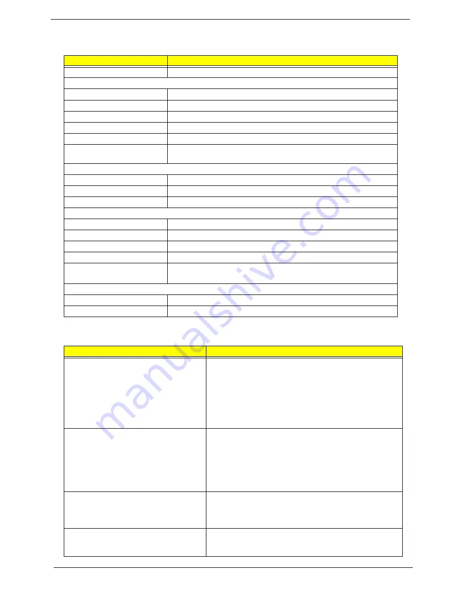
AC Adapter
Item
Specification
Vendor & model name
Liton, 135W power supply
Input Voltage
Low Range
90(min.)/137(max.)/100-127(nominal)
High Range
180(min.)/265(max.)200-240(nominal)
Input current
2.2A(max)
Nominal frequency (Hz)
50-60
Frequency variation range (Hz)
47-63
Efficiency
It should provide an efficiency of 85% minimum, when measured at maximum
load under 115Vac.
Output Requirements
DC output voltage
19V
Noise + Ripple
380mV as output voltage is 19V
Peak Load
18.5V-19.71V
Dynamic Output Characteristics
Turn-on delay time
5 sec (@ 115Vac)
Hold up time
5ms (@115Vac, Full load)
Over Voltage Protection (OVP)
29V
Short circuit protection
9.5A @19V output voltage
Electrostatic discharge (ESD)
15KV (at air discharge)
8KV (at contact discharge)
Dielectric Withstand Voltage
Primary to secondary
2150VDC for 1 sec.
Ground leakage current
less than 250uA
Power Management
Power Saving Mode
Phenomenon
Standby Mode
Enter Standby Mode when
1.Standby/Hibernation hot-key is pressed
and system is not ready to enter Hibernation
mode.
2.System standby/ Hibernation timer expires
and system is not ready to enter Hibernation
mode.
T
The buzzer beeps
T
The Sleep indicator lights up
Hibernation Mode
Enter Hibernation Mode (suspend to HDD)
when
1.Hibernation hot-key is pressed and
system is ready to enter Hibernation mode
2.System Hibernation timer expires and
system is ready to enter Hibernation mode.
T
All power shuts off
Display Standby Mode
Keyboard, built-in touchpad, and an external
PS/2 pointing device are idle for a specified
period.
T
The display shuts off
Hard Disk Standby Mode
Hard disk is idle within a specified period of
time.
T
Hard disk drive is in standby mode.
(spindle turned-off)
Содержание Aspire 1620 Series
Страница 1: ...Aspire 1620 Series Service Guide PRINTED IN TAIWAN ...
Страница 6: ...VI ...
Страница 9: ...IX Appendix C Online Support Information 122 Index 124 ...
Страница 42: ...Chapter 1 33 ...
Страница 67: ...Chapter 3 58 ...
Страница 107: ...Chapter 4 98 8 You will see the screen displaying PASS when the system has buit NAPP Master hard disc drive ...
Страница 108: ...99 Aspire 1620 ...
Страница 112: ...103 Aspire 1620 Aspire 1620 Exploded Diagram ...
Страница 124: ...115 Aspire 1620 ...
Страница 130: ...121 Aspire 1620 ...
Страница 132: ...123 Appendix C ...