background image

75

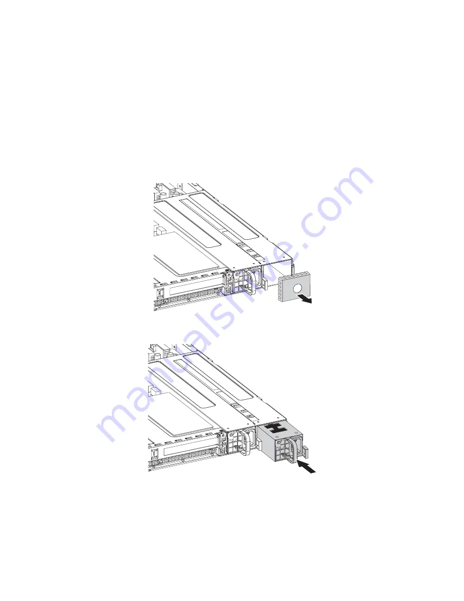
To install a second power supply module:

1

Observer the ESD precautions described on page 35.

2

If a filler panel is installed, remove the filler panel. 

(1) Using your thumb and index finger, squeeze the filler panel 

latch to release the filler panel from the chassis.  

(2) Pull the filler panel out of the power supply module bay. 

3

Insert the new power supply module into the empty module bay, 
until it locks into place.  

Содержание Altos R520 M2

Страница 1: ...Acer Altos R520 M2 Series User s Guide ...

Страница 2: ...Model Name Acer Altos R520 M2 Part Number Purchase Date Place of Purchase Copyright 2009 All Rights Reserved Acer Altos R520 M2 Series User s Guide ...

Страница 3: ...ing power to the power supply unit Install the power supply unit before connecting the power cord to the AC power outlet Unplug the power cord before removing the power supply unit from the computer If the system has multiple sources of power disconnect power from the system by unplugging all power cords from the power supplies CAUTION for accessibility Be sure that the power outlet you plug the p...

Страница 4: ...ed from the type of power indicated on the marking label If you are not sure of the type of power available consult your dealer or local power company Do not allow anything to rest on the power cord Do not locate this product where people will walk on the cord If an extension cord is used with this product make sure that the total ampere rating of the equipment plugged into the extension cord does...

Страница 5: ... the wall outlet and refer servicing to qualified service personnel when the power cord or plug is damaged cut or frayed liquid was spilled into the product the product was exposed to rain or water the product has been dropped or the case has been damaged the product exhibits a distinct change in performance indicating a need for service the product does not operate normally after following the op...

Страница 6: ...more information on the Waste from Electrical and Electronics Equipment WEEE regulations visit http www acer group com public Sustainability sustainability01 htm Mercury advisory For projectors or electronic products containing an LCD CRT monitor or display Lamp s inside this product contain mercury and must be recycled or disposed of according to local state or federal laws For more information c...

Страница 7: ...these symptoms or any other recurring or persistent discomfort and or pain related to computer use consult a physician immediately and inform your company s health and safety department The following section provides tips for more comfortable computer use Finding your comfort zone Find your comfort zone by adjusting the viewing angle of the monitor using a footrest or raising your sitting height t...

Страница 8: ...vel than the top edge of the display so your eyes point downward when looking at the middle of the display Adjust the display brightness and or contrast to a comfortable level for enhanced text readability and graphics clarity Eliminate glare and reflections by placing your display in such a way that the side faces the window or any light source minimizing room light by using drapes shades or blin...

Страница 9: ...e short breaks regularly and often Perform some stretching exercises Breathe fresh air as often as possible Exercise regularly and maintain a healthy body Warning We do not recommend using the computer on a couch or bed If this is unavoidable work for only short periods take breaks regularly and do some stretching exercises ...

Страница 10: ...and Iceland and Liechtenstein This device must be used in strict accordance with the regulations and constraints in the country of use For further information please contact local office in the country of use Laser compliance statement The CD or DVD drive used with this computer is a laser product The CD or DVD drive s classification label shown below is located on the drive Class 1 Laser Product ...

Страница 11: ...d mouse set EN301 489 17 V1 2 1 Article 3 2 Spectrum Usages EN300 440 2 V1 1 2 Applicable to non bluetooth wireless keyboard mouse set EN300 328 V1 7 1 EN301 893 V1 4 1 Applicable to 5GHz high performance RLAN for EU nations only List of applicable countries EU member states as of May 2004 are Belgium Denmark Germany Greece Spain France Ireland Italy Luxembourg the Netherlands Austria Portugal Fin...

Страница 12: ...tive 2004 108 EC as attested by conformity with the following harmonized standards EN55022 2006 AS NZS CISPR22 2006 Class B EN55024 1998 A1 2001 A2 2003 EN55013 2001 A1 2003 A2 2006 Applicable to product built with TV tuner module EN55020 2007 Applicable to product built with TV tuner module EN61000 3 2 2006 Class D EN61000 3 3 1995 A1 2001 A2 2005 Low Voltage Directive 2006 95 EC as attested by c...

Страница 13: ...llowing harmonized standard Article 3 1 a Health and Safety EN60950 1 2001 A11 2004 EN50371 2002 Article 3 1 b EMC EN301 489 1 V1 6 1 EN301 489 3 V1 4 1 Applicable to non bluetooth wireless keyboard mouse set EN301 489 17 V1 2 1 Article 3 2 Spectrum Usages EN300 440 2 V1 1 2 Applicable to non bluetooth wireless keyboard mouse set EN300 328 V1 7 1 EN301 893 V1 4 1 Applicable to 5GHz high performanc...

Страница 14: ...xiv ...

Страница 15: ...European Union EU xi 1 System tour 1 System features 3 Performance 3 Mechanical 6 Environmental 7 External and internal structure 8 Front bezel 8 Front panel 9 Rear panel 11 Internal components 12 System boards 13 Mainboard 13 Backplane board 18 Riser board 20 System LED indicators 21 Front panel LED indicators 21 Hot plug HDD carrier LED indicators 23 LAN port LED indicators 24 2 System setup 25 ...

Страница 16: ...essor configuration guidelines 55 Upgrading the system memory 60 Installing an expansion card 70 Installing the TPM module 73 Installing and removing a power supply module 74 4 System BIOS 77 BIOS overview 79 Entering BIOS setup 80 BIOS setup primary menus 80 BIOS setup navigation keys 81 Main menu 82 Advanced menu 83 Processor Configuration 84 Memory Configuration 90 Advanced Chipset Configuratio...

Страница 17: ...rd SATA RAID Configuration Utility 134 LSI MegaRAID SAS RAID Configuration Utility 137 Promise RAID Configuration Utility 139 Appendix B Rack mount configuration 141 Rack installation information 143 System rack installation 145 Vertical mounting hole pattern 146 Installing the system into the rack 147 Appendix C Altos eXpress Console 155 Altos eXpress Console 157 Features 157 Software installatio...

Страница 18: ...iii Server Health 170 Configuration 172 Remote Control 185 Maintenance 188 Logout 190 KVM Remote Console utility 191 Menu bar 192 Video 192 Keyboard 193 Mouse 194 Option 194 Device 194 Help 195 Index 197 ...

Страница 19: ...1 System tour ...

Страница 20: ...This chapter provides a brief overview of the system hardware including illustrations with component identification ...

Страница 21: ...yper Threading Technology Extended Memory 64 bit Technology Chipset IOH Intel 5520 chipset ICH Intel ICH10R Memory Twelve DDR3 1333 MHz ECC unbuffered registered DIMMs six DIMMs per processor supporting Six channel memory bus three channels per processor 1 to 8 GB registered DIMMs RDIMM for up to 96 GB of total system memory or 1 to 4 GB unbuffered DIMMs UDIMM for up to 48 GB of total system memor...

Страница 22: ...t Ethernet LAN ports RJ 45 Supports Intel I O Acceleration Technology Supports boot from iSCSI One dedicated 10 100 Fast Ethernet port for BMC baseboard management controller and server management SAS SATA support Embedded SATA2 controller with six onboard ports Supports RAID 0 1 10 Optional Promise 4 port SAS HBA Support RAID 0 1 Optional LSI 8 port SAS RAID card Supports RAID 0 1 10 5 6 Backup b...

Страница 23: ...2 support Integrated Baseboard Management Controller BMC Intelligent Platform Management Interface IPMI 2 0 compliant In band and out band server management Dedicated NIC port for remote management Built in Altos eXpress Console for server management Supports KVM over IP USB mouse keyboard and media redirection Acer EasyBuild v9 0 Acer Server Manager ASM 3 Media storage Slim DVD writer Supports up...

Страница 24: ...rosoft Windows Server 2003 x64 Edition Microsoft Windows Server 2003 Red Hat Enterprise Linux 5 0 EM64T Red Hat Enterprise Linux 5 0 SUSE Linux Enterprise Server 10 EM64T SUSE Linux Enterprise Server 10 VMware ESXi 4 VMware ESX 4 Mechanical Chassis Rack mount 1U tray less setup option With Altos R series tool less sliding rail and cable arm Weight 12 4 kg 4 Dimensions 43 5 H x 430 W x 745 D mm wit...

Страница 25: ...7 Environmental Temperature Operating 0 to 40 C 0 to 30 C when SAS RAID cards are installed Non operating 20 to 70 C Humidity non operating 90 non condensing 35 C ...

Страница 26: ... Icon Component 1 LAN1 activity indicator 2 LAN2 activity indicator 3 HDD activity indicator 4 Sysrem status indicator 5 System ID indicator 6 Power status indicator 7 Security keylock This lock on the front bezel prevents unauthorized access for maximum security ...

Страница 27: ...m optical drive 3 Optical drive status indicator 4 Optical drive eject button 5 Power status indicator button 6 System ID indicator button 7 LAN1 status indicator 8 LAN2 status indicator 9 Hard disk drive HDD activity indicator 10 System status indicator ...

Страница 28: ...nterrupt NMI button Puts the server in a halt state for diagnostic purposes and allows the service technician to generate a NMI to the processor to help debug server errors 12 USB 2 0 port 13 2 5 inch hot plug HDD bay No Icon Component ...

Страница 29: ...nt port RJ 45 10 100 Mbps 5 Low profile PCI expansion slot 6 Full height PCI expansion slot 7 Power supply module 8 Power supply module bay Accommodates an optional hot swap redundant power supply module 9 System ID indicator button 10 USB 2 0 ports 11 Monitor port 12 LAN2 port 10 100 1000 Mbps 13 PS2 keyboard port ...

Страница 30: ... Component 1 Dual rotor fan module 2 Power supply module 3 Mainboard 4 PCI riser board bracket assembly 5 Processor 1 6 Memory slots for Processor 1 7 Memory slots for Processor 2 8 Processor 2 9 Air duct 10 Optical drive 11 Hard disk drives ...

Страница 31: ...13 System boards Mainboard The mainboard becomes accessible once you open the system It should look like the figure shown below ...

Страница 32: ... 4 USB 2 0 ports 9 SW1 ID switch 10 TPM_20 TPM connector 11 COMB Serial port connector 12 CPU2 Processor 2 socket 13 DIMMD1 D2 DIMME1 E2 DIMMF1 F2 DDR3 sockets for processor 2 14 CPU1 Processor 1 socket 15 SSI_2X4P2 8 pin power connector 16 DIMMA1 A2 DIMMB1 B2 DIMMC1 C2 DDR3 sockets for processor 1 17 F_USB1 USB cable connector for tape drive 18 F_PANEL1 Front panel connector 19 J2 SMBUS connector...

Страница 33: ...GPIO_JP2 SGPIO connector for backplane SAS SATA connector 2 29 USB_A1 USB type A connector 30 SATA3 SATA 3 connector 31 SATA2 SATA 2 connector 32 PSMI1 PSMI power supply management interface connector 33 U60 Intel ICH10R 34 F_USB2 Front USB cable connector 35 CLR_RTC Clear RTC jumper Close 1 2 Normal operation default Close 2 3 Clear RTC status 36 CLR_CMOS Clear CMOS jumper Close 1 2 Normal operat...

Страница 34: ...rd jumper Close 1 2 Normal operation default Close 2 3 Clear Supervisor Password in BIOS setup menu 46 U190 Winbond W83792G chipset 47 PCI EX8_RU PCI EX8_RD Full height PCI E riser slot 48 J1 AMI Pilot II firmware upgrade connector 49 JP_STRP8 BMC firmware upgrade jumper Close 2 3 Default setting 50 JP_STRP2 BMC firmware upgrade jumper Close 2 3 Default setting 51 PILOT_DIS BMC force mode jumper C...

Страница 35: ...17 54 U23 Broadcom BCM5221PHY chipset 55 U6 Intel 82576EB GbE chipset No Code Description ...

Страница 36: ...ector to mainboard 3 SAS CON2 SAS data cable connector 2 4 J12 Debug port 5 SAS CON1 SAS data cable connector 1 6 SGPIO_JP2 SGPIO jumper block 7 P2 Power cable connector 8 FAN_1A Fan 1A cable connector 9 FAN_1B Fan 1B cable connector 10 SGPIO_J1 SGPIO jumper block 11 FAN_2A Fan 2A cable connector 12 FAN_2B Fan 2B cable connector 13 FAN_3A Fan 3A cable connector 14 FAN_3B Fan 3B cable connector 15 ...

Страница 37: ...e connector 18 FAN_5A Fan 5A cable connector 19 FAN_6A Fan 6A cable connector 20 FAN_6B Fan 6B cable connector 21 J21 LED power select jumper Close 1 2 No change 22 J27 HDD tray LED conduct jumper setting Close 1 2 Two LEDs display default No Code Description ...

Страница 38: ...assembly provides support for both full height and low profile expansion cards Full height riser board Low profile riser board No Code Description 1 PCI_1 PCI Express 2 0 x16 slot PCI Express 2 0 x16 throughput No Code Description 1 PCI_2 PCI Express 2 0 x8 slot PCI Express 2 0 x8 throughput ...

Страница 39: ... Knowing what each LED indicator signifies can aid in problem diagnosis and troubleshooting Front panel LED indicators The following table list and describe the LED indicators available on the front panel No Indicator Color State Description 1 System ID Blue On System identification is active Off System identification is disabled ...

Страница 40: ... LAN2 activity Green On Link between system and network or no access Blink Network access 5 HDDactivity Green Blink HDD access N A Off No access 6 System status Green On Running or normal operation Blink System degraded due to CPU or DIMM error Amber On Critical or non recoverable condition Power modules or voltage power supply failure or critical temperature Blink Non critical condition N A Off S...

Страница 41: ...DD carrier LED indicators Description 1 2 Green Red HDD present On Off HDD access Blink 4 Hz Off HDD failure Off On HDD removed Off On HDD connected and rebuilding data On Blink 1 Hz HDD locate Blink 4 Hz Blink 4 Hz ...

Страница 42: ...tion 1 Link activity indicator Green On Network link is detected Blink Transmit or receive activity 2 Speed indicator N A Off 10 Mbps connection Green On 100 Mbps connection Yellow On 1000 Mbps connection Note The server management port does not support 1000 Mbps connection ...

Страница 43: ...2 System setup ...

Страница 44: ...This chapter gives you instructions on how to set up the system Procedures on how to connect peripherals are also explained ...

Страница 45: ...nd dust free Stable surface free from vibration Well ventilated and away from sources of heat Secluded from electromagnetic fields produced by electrical devices such as air conditioners radio and TV transmitters etc Checking the package contents Check the following items from the package Acer Altos R520 M2 system Acer Altos R520 M2 accessory box If any of the above items are damaged or missing co...

Страница 46: ...240 VAC only Do not connect the system to an incorrect voltage source Refer to the illustration below for specific connection instructions on the peripherals you want to connect to the system Note Consult the operating system manual for information on how to configure the network setup ...

Страница 47: ...stem starts up and displays a welcome message on the monitor After that a series of POST messages appears The POST messages indicate if the system is running well or not Note If the system does not turn on or boot after pressing the power button go to the next section for the possible causes of the boot failure Aside from the POST messages you can determine if the system is in good condition by ch...

Страница 48: ...nnected to the power source and to the AC input connector No power comes from the grounded power outlet Have an electrician check your power outlet Loose or improperly connected internal power cables Check the internal cable connections If you are not confident to perform this step ask a qualified technician to assist you Warning Make sure all power cords are disconnected from the electrical outle...

Страница 49: ...side of the disc facing upward Note When handling the disc hold it by the edges to avoid smudges or fingerprints 4 Gently press the disc down to make sure that it is properly inserted Caution While pressing the disc be careful not to bend the disc tray Make sure that the disc is properly inserted before closing the disc tray Improper insertion may damage both the disc and the CD ROM drive 5 Gently...

Страница 50: ...to the related user documentation To turn off the system via software 1 Press the Ctrl Alt Delete on the attached keyboard or click the Start on the Windows taskbar 2 Select Shut Down 3 Select Shut down from the drop down window then click on OK To turn off the system via hardware If you cannot shut down the server using the software press the power button for at least four seconds Quickly pressin...

Страница 51: ...3 System upgrade ...

Страница 52: ...This chapter discusses the precautionary measures and installation procedures you need to know to upgrade the system ...

Страница 53: ...ecautions before you install a server component Do not remove a component from its protective packaging until you are ready to install it Do not touch the component pins leads or circuitry Components with a Printed Circuit Board PCB assembly should always be laid with the assembly side down Wear a wrist grounding strap and attach it to a metal part of the server before handling components If a wri...

Страница 54: ...bles from the power outlets 3 Disconnect all telecommunication cables from their ports 4 Place the system unit on a flat stable surface 5 Open the system according to the instructions on page 37 6 Follow the ESD precautions described in this section when handling a server component Post installation instructions Perform the steps below after installing a server component 1 See to it that all compo...

Страница 55: ...stall additional components The front bezel and top cover are removable to allow access to the system s internal components Refer to the following sections for instructions Removing and installing the front bezel To remove the front bezel 1 If necessary unlock the front bezel 1 Insert the key into the lock 2 Turn the key counterclockwise to the unlocked position Make sure the small colored dot is ...

Страница 56: ... 2 Grasp the front bezel at the outer edge and pull it straight out To install the front bezel 1 Align the notch on left side of the bezel to the guides on the rack handle 2 Snap the bezel to the right side of the chassis ...

Страница 57: ...s described on page 35 2 Remove the top cover 1 Remove the two screws located on the top cover 2 Press and hold the release button 3 Slide the cover toward the back of the chassis until the cover disengage with the slots on the chassis 4 Lift the top cover away from the server 3 Put the top cover aside for reinstallation later ...

Страница 58: ...structions described on page 35 2 Install the top cover 1 Place the top cover on the chassis so that the tabs on the cover align with the slots on the chassis 2 Slide the top cover toward the front of the chassis until it is fully closed 3 Replace the two screws on the top cover ...

Страница 59: ...ensure reliable and continued operation You need to remove the air duct to perform the following procedures Removing and installing a processor Removing and installing a memory module To remove the air duct 1 Perform the pre installation instructions described on page 35 2 Lift the air duct from the chassis ...

Страница 60: ...structions described on page 35 2 Place the air duct on the chassis so that the tabs on the air duct align with the slots on the chassis Caution Do not pinch or unplug cables that may be near or under the air duct 3 Observe the post installation instructions described on page 36 ...

Страница 61: ...rive Use only Acer qualified SAS or SATA HDDs To purchase a SAS or SATA HDD contact your local Acer representative Before removing a hard disk drive make sure to back up all important system files Check hard disk drive status by checking the status LED indicators on the HDD carrier The hard disk drives must be installed in the following order Determining drive status Each HDD carrier features two ...

Страница 62: ...ing the drive status LEDs 4 Remove the HDD carrier 1 Unlock the HDD carrier latch 2 Press the HDD carrier latch 3 Pull the lever and slide the carrier from the chassis 5 Observe the post installation instructions described on page 36 For instructions on how to install a new hard disk refer to the next section To install an HDD Note To purchase an HDD carrier contact your local Acer representative ...

Страница 63: ...affle to the HDD carrier 2 Remove the air baffle from the HDD carrier 3 Save the air baffle and screws for later use 3 Remove the new HDD from its protective packaging 4 Install the new HDD to the HDD carrier 1 Place the HDD into the HDD carrier 2 Secure it with the four screws that came with the HDD carrier ...

Страница 64: ...ith the lever still extended slide the HDD carrier all the way into the drive bay 2 Use the lever to push the HDD carrier until it locks into place then close the HDD carrier lever 3 Lock the HDD carrier 6 Observe the post installation instructions described on page 36 ...

Страница 65: ...ons described on page 35 2 Remove the front bezel Perform the instructions described in To remove the front bezel section on page 37 3 If a filler panel is installed remove it from the drive bay 4 Remove the access panel and optical drive tray 1 Remove the four screws that secure the access panel to the chassis 2 Slide the access panel to disengage from the chassis then lift the access panel off t...

Страница 66: ... tray out through the front of the server 5 Remove the new drive from its protective packaging 6 Install the optical drive 1 Slide the optical drive into the drive tray 2 Secure it with the four screws that came with the optical drive kit ...

Страница 67: ...Connect the SATA ODD cable to the optical drive 8 Install the access panel 1 Place the access panel on the chassis so that the tabs on the panel align with the slots on the chassis then slide the panel toward the front of the chassis until it is fully closed 2 Replace the four screws on the access panel 9 Observe the post installation instructions described on page 36 ...

Страница 68: ...ezel Perform the instructions described in To remove the front bezel section on page 37 3 Remove the access panel 1 Remove the four screws that secure the access panel to the chassis 2 Slide the access panel to disengage from the chassis then lift the access panel off the chassis 3 Put the access panel aside for reinstallation later ...

Страница 69: ...3 Slide the drive tray out through the front of the server 5 Remove the optical drive 1 Remove the four screws that secure the optical drive to the drive tray 2 Slide the optical drive out of the drive tray 6 Observe the post installation instructions described on page 36 If installing a new optical drive see To install an optical drive section on page 47 section ...

Страница 70: ...ol Fan cable connectors Refer to the following illustration for location of the dual rotor fan modules and fan cable connectors To replace a dual rotor fan module 1 Perform the pre installation instructions described on page 36 Warning The system fan becomes very hot when the system is on Allow it to cool off first before handling 2 Identify the defective fan ...

Страница 71: ...53 3 Remove the fan module 1 Disconnect the two fan cables 2 Press the release tabs on the fan module and pull it up and away from the chassis ...

Страница 72: ... 4 Install the new dual rotor fan module 1 Slide the new fan into the chassis 2 Connect the two fan cables Check the routing of all cables for obstructions 5 Observe the post installation instructions described on page 36 ...

Страница 73: ...ving a processor make sure to back up all important system files When installing a second processor make sure it has same stepping and frequency specifications as the default processor Handle the processor and the heat sink carefully Damage to either may prevent the system from functioning properly To upgrade the default processor 1 Perform the pre installation instructions described on page 35 Wa...

Страница 74: ... patch touch the work surface 4 Use an alcohol prep pad to wipe off the thermal grease from both the heat sink and the processor socket retention plate 4 Remove the default processor Warning The processor becomes very hot when the system is on Allow it to cool off first before handling 1 Release then lift the load lever 2 Open the retention plate to expose the socket body ...

Страница 75: ...tall the new processor 1 Hold the processor by its edges Make sure the alignment tabs on the socket fit the two notch located on the edge of the processor The pins are keyed in such a way that you cannot install the processor in the wrong orientation without bending the pins 2 Insert the new processor in the socket 3 Close the retention plate 4 Engage the load lever back into place ...

Страница 76: ...ink Caution The heat sink has a thermal interface material TIM on the underside Use caution so that you do not damage the TIM If a protective film is installed on the TIM remove it 1 Set the heat sink over the processor aligning the four captive screws with the four screw posts surrounding the processor 2 Loosely screw in the captive screws on the heat sink corners in a diagonal manner Note Do not...

Страница 77: ...nstallation 1 Refer to steps 4 1 and 4 2 of the previous section 2 Remove the socket cap from the processor socket 3 Install the new processor Refer to steps 6 and 7 of the previous section 4 Install the heat sink Refer to step 8 of the previous section 5 Observe the post installation instructions described on page 36 ...

Страница 78: ...pport three channel DDR3 133 registered unbuffered ECC memory modules For processor 1 it will be channels A B and C and for processor 2 it will be channels D E and F Each channel is divided into two sockets Socket 1 and Socket 2 Socket 1 slots are colored blue and comprised of DIMM slots A1 B1 C1 D1 E1 and F1 and Socket 2 slots are colored black and comprised of DIMM slots A2 B2 C2 D2 E2 and F2 Fo...

Страница 79: ...a single processor configuration you should install the memory module into DIMM A1 to DIMM C2 slots The DIMM D1 to DIMM F2 slots are enabled when a second processor is installed on the mainboard DIMM modules of the same type size and manufacturer must be installed in the same colored DIMM slots Follow the population sequence illustrated in the next section when installing a memory module ...

Страница 80: ...availability Total Capacity DIMM A2 DIMM A1 DIMM B2 DIMM B1 DIMM C2 DIMM C1 1GB 1GB 2GB 1GB 1GB 3GB 1GB 1GB 1GB 4GB 1GB 1GB 1GB 1GB 6GB 1GB 1GB 1GB 1GB 1GB 1GB 2GB 2GB 4GB 2GB 2GB 6GB 2GB 2GB 2GB 8GB 2GB 2GB 2GB 2GB 12GB 2GB 2GB 2GB 2GB 2GB 2GB 4GB 4GB 8GB 4GB 4GB 12GB 4GB 4GB 4GB 16GB 4GB 4GB 4GB 4GB 24GB 4GB 4GB 4GB 4GB 4GB 4GB 8GB 8GB 16GB 8GB 8GB 24GB 8GB 8GB 8GB 32GB 8GB 8GB 8GB 8GB 48GB 8GB ...

Страница 81: ...B 12GB 2GB 2GB 2GB 2GB 2GB 2GB 16GB 2GB 2GB 2GB 2GB 2GB 2GB 2GB 2GB 18GB 2GB 2GB 2GB 2GB 2GB 2GB 2GB 2GB 2GB 24GB 2GB 2GB 2GB 2GB 2GB 2GB 2GB 2GB 2GB 2GB 2GB 2GB 4GB 4GB 4GB 12GB 4GB 4GB 4GB 16GB 4GB 4GB 4GB 4GB 24GB 4GB 4GB 4GB 4GB 4GB 4GB 32GB 4GB 4GB 4GB 4GB 4GB 4GB 4GB 4GB 36GB 4GB 4GB 4GB 4GB 4GB 4GB 4GB 4GB 4GB 48GB 4GB 4GB 4GB 4GB 4GB 4GB 4GB 4GB 4GB 4GB 4GB 4GB 16GB 8GB 8GB 24GB 8GB 8GB 8G...

Страница 82: ...r channels D E and F of processor 2 socket The effective memory size is reduced by at least one half in mirrored memory configuration Mirrored memory configuration Single processor configuration M stands for Mirror Processor 1 Processor 2 Total Memory DIMM A1 DIMM A2 DIMM B1 DIMM B2 DIMM C1 DIMM C2 DIMM D1 DIMM D2 DIMM BE DIMM E2 DIMM F1 DIMM F2 Physical Memory Detecte d by OS 1GB 1GB M 2GB 1GB 1G...

Страница 83: ... 1GB 1GB M 1GB M 1GB 1GB M 6GB 3GB 1GB 1GB 1GB M 1GB M 1GB 1GB 1GB M 1GB M 8GB 4GB 2GB 2GB M 2GB 2GB M 8GB 4GB 2GB 2GB 2GB M 2GB M 2GB 2GB 2GB M 12GB 6GB 2GB 2GB 2GB M 2GB M 2GB 2GB 2GB M 2GB M 16GB 8GB 4GB 4GB M 4GB 4GB M 16GB 8GB 4GB 4GB 4GB M 4GB M 4GB 4GB 4GB M 24GB 12GB 4GB 4GB 4GB M 4GB M 4GB 4GB 4GB M 4GB M 32GB 16GB 8GB 8GB M 8GB 8GB M 32GB 16GB 8GB 8GB 8GB M 8GB M 8GB 8GB 8GB M 48GB 24GB ...

Страница 84: ... 2GB 2GB 2GB 8GB 8GB 4GB 4GB 8GB 8GB 4GB 4GB 4GB 4GB 16GB 16GB 8GB 8GB 16GB 16GB 8GB 8GB 8GB 8GB 32GB 32GB Processor 1 Processor 2 Total Memory DIMM A1 DIMM A2 DIMM B1 DIMM B2 DIMM C1 DIMM C2 DIMM D1 DIMM D2 DIMM BE DIMM E2 DIMM F1 DIMM F2 Physical Memory Detecte d by OS 1GB 1GB 1GB 1GB 4GB 4GB 1GB 1GB 1GB 1GB 1GB 1GB 6GB 6GB 1GB 1GB 1GB 1GB 1GB 1GB 1GB 1GB 8GB 8GB 2GB 2GB 2GB 2GB 8GB 8GB 2GB 2GB ...

Страница 85: ...o the sockets 2 Push the DIMM to the socket until the retaining clips snap inward Note The DIMM slot is slotted to ensure proper installation If you insert a DIMM but it does not fit easily into the socket you may have inserted it incorrectly Reverse the orientation of the DIMM and insert it again 5 Observe the post installation instructions described on page 36 6 Reconfigure the system memory See...

Страница 86: ...he DIMM slots Perform the instructions described in To remove the air duct section on page 41 3 Remove the memory module 1 Press the holding clips on both sides of the DIMM slot outward to release the DIMM 2 Gently pull the DIMM upward to remove it from the DIMM slot 4 If you intend to install a new DIMM refer to previous section for related procedure otherwise reinstall the air duct then observe ...

Страница 87: ...69 To reconfigure the system memory The system automatically detects the amount of memory installed Run the BIOS setup to view the new value for total system memory and make a note of it ...

Страница 88: ...I Express 2 0 x8 throughput Caution The PCI riser board bracket assembly must be installed to maintain proper airflow inside the server To install an expansion card 1 Perform the pre installation instructions described on page 35 2 Remove the PCI riser board bracket assembly 1 Remove the three screws on the PCI riser board bracket assembly 2 Gently pull the bracket assembly to disengage from the c...

Страница 89: ...store it for reassembly later Caution Do not discard the slot cover If the expansion card is removed in the future the slot cover must be reinstalled to maintain proper system cooling 5 Install the expansion card 1 Align and insert the expansion card until it seats in the slot bracket 2 Secure the card with the screw removed earlier ...

Страница 90: ...mbly over the PCI riser slot on the mainboard then push the bracket assembly down until it is securely seated 2 Secure the bracket assembly to the chassis with the three screws 7 Connect the cables to the installed expansion card 8 Observe the post installation instructions described on page 36 ...

Страница 91: ... on page 35 2 Locate the TPM module connector If necessary remove any boards or cables that prevent access to it 3 Remove the TPM module from its protective packaging handling it by the edges 4 Install the TPM module Insert the TPM module into the TPM module connector 5 Observe the post installation instructions described on page 42 6 Enable the TPM in BIOS Refer to Security menu on page 107 for m...

Страница 92: ...ower supply module You can also consider wearing protective gloves WARNING To reduce the risk of personal injury from electric shock hazards do not open the power supply modules There are no serviceable parts inside the module Caution Electrostatic discharge can damage electronic components Make sure that you are properly grounded before handling a power supply module Caution Due to chassis airflo...

Страница 93: ...ler panel is installed remove the filler panel 1 Using your thumb and index finger squeeze the filler panel latch to release the filler panel from the chassis 2 Pull the filler panel out of the power supply module bay 3 Insert the new power supply module into the empty module bay until it locks into place ...

Страница 94: ...upply modules installed determine which power supply module has failed 2 Remove the AC power cord from the power supply being replaced 3 Remove the power supply module 1 Press the power supply latch to release the power supply module from the chassis 2 Use the handle to pull the power supply module out of the server 4 Install a new power supply module or install a filler panel to the empty bay ...

Страница 95: ...4 System BIOS ...

Страница 96: ...This chapter gives information about the system BIOS and discusses how to configure the system by changing the settings of the BIOS parameters ...

Страница 97: ...essage to make changes to the BIOS setup Note If you repeatedly receive Run Setup messages the battery may be bad In this case the system cannot retain configuration values in CMOS Ask a qualified technician for assistance BIOS setup loads the configuration values in a battery backed nonvolatile memory called CMOS RAM This memory area is not part of the system RAM which allows configuration data t...

Страница 98: ...d to restart the server The Setup Main menu will be displayed showing the Setup s menu bar Use the left and right arrow keys to move between selections on the menu bar BIOS setup primary menus The tabs on the Setup menu bar correspond to the six primary BIOS Setup menus namely Main Advanced Power Security Server Boot Exit In the descriptive table following each of the menu screenshots settings in ...

Страница 99: ...rently selected field only if it is user configurable Press these keys repeatedly to display each possible entry or the Enter key to choose from a pop up menu Note Grayed out fields are not user configurable Enter key Display a submenu screen Note Availability of submenu screen is indicated by a Esc If you press this key On one of the primary menu screens the Exit menu displays On a submenu screen...

Страница 100: ...wing the hour minute second format BIOS Version Indicates the version number of the BIOS setup utility BIOS Date Indicates the date when the BIOS setup utility was created CPU Type CPU Speed CPU Count Indicates the technical specifications for the installed processor Total Memory Size Indicates the total size of system memory detected during POST ...

Страница 101: ...enu display submenu options for configuring the function of various hardware components Select a submenu item then press Enter to access the related submenu screen Note Setup options may vary depending on your hardware configuration ...

Страница 102: ...4 System BIOS 84 Processor Configuration ...

Страница 103: ...ion cycles per second The faster the clock the more instructions the CPU can execute per second Processor CPUID Indicates the processor ID number Processor L2 Cache Indicates the processor 2nd level cache size detected during POST Processor L3 Cache Indicates the processor 3rd level cache size detected during POST QPI Frequency Displays the QuickPath Interconnect QPI frequency Multiprocessor Speci...

Страница 104: ... processor s Note Changing this feature may affect system performance Enabled Disabled Adjacent Cache Line Prefetch When Enabled cache lines are fetched in pairs even line odd line When Disabled only current cache line required is fetched Note Changing this feature may affect system performance Enabled Disabled CPU Thermal Trip Enables or disables CPU thermal trip Enabled Disabled BMC Action for C...

Страница 105: ... A20M support Enabled Disabled Machine Checking Enables or disables machine checking Enabled Disabled Fast String Operations Enables or disables fast string operations Enabled Disabled Set Max Ext CPUID 3 Sets the max CPUID extended function value to 3 Enabled Disabled Echo TPR Enables or disables External Task Priority Register xTPR messages to be transmitted on the system bus to the central agen...

Страница 106: ...ed Disabled EIST GV3 Enables or disables EIST GV3 Enabled Disabled EIST PSD Function Sets the EIST PSD Function SW_ALL SW_ANY HW_ALL Turbo mode Enables or Disables the Turbo Mode Enabled Disabled T State Enables or Disables the T State Enabled Disabled CPU C State Enables or Disables the CPU C State Enabled Disabled CPU C1E Enables or Disables the CPU C1E Enabled Disabled ...

Страница 107: ...U C6 Report Enables or Disables the CPU C6 report Enabled Disabled CPU C7 Report Enables or Disables the CPU C7 report Enabled Disabled Package C State Limit Sets the Package C State Limit C0 C1 C3 C6 C7 No Limit ACPI MWAIT Extensions Enables or Disables the ACPI MWAIT extensions Enabled Disabled Parameter Description Option ...

Страница 108: ...4 System BIOS 90 Memory Configuration ...

Страница 109: ...slots Memory Retest Select whether to delete the historical memory data log System memory will be retested on the next boot up Yes No Memory Control Settings Sets the memory control settings Auto Manual Memory RAS Mode Sets the memory RAS mode Independent Mirror Lock Spare Memory Frequency Sets the memory frequency Auto DDR3 800 DDR3 1067 DDR3 1333 Channel Interleave setting Sets the channel inter...

Страница 110: ...4 System BIOS 92 Advanced Chipset Configuration ...

Страница 111: ...d IOH IOxAPIC Enables or Disables the IOH IOxAPIC Enabled Disabled 4GB PCI Hole Granularity Sets the 4GB PCI Hole Granularity 512 MB 1 0 GB 2 0 GB QPI Control Settings Enables or Disables the QPI Control Setting Enabled Disabled QPI Link Fast Mode Enables or Disables the QPI Link Fast Mode Enabled Disabled QPI Frequency Selection Sets the QPI Frequency Selection Auto 4 800GT 5 866GT QPI Isoch Supp...

Страница 112: ...Correctable Error UnCorrectab le Error Both ECC Threshold Sets the ECC Threshold 0 Uncorrectable pass to OS Enables or Disables the UnCorrectable Pass to OS Enabled Disabled Enable Multimedia Timer When set to yes Multimedia Timer is enabled Yes No Parameter Description Option ...

Страница 113: ...95 Intel VT for Directed I O VT d Parameter Description Option Intel VT for Directed I O VT d Enables or disables the Intel Virtualization Technology for Directed I O VT d Enabled Disabled ...

Страница 114: ...nabled Disabled VT d for Port 3 Enables or disables VT d support for port 3 Enabled Disabled VT d for Port 4 Enables or disables VT d support for port 4 Enabled Disabled VT d for Port 5 Enables or disables VT d support for port 5 Enabled Disabled VT d for Port 6 Enables or disables VT d support for port 6 Enabled Disabled VT d for Port 7 Enables or disables VT d support for port 7 Enabled Disabled...

Страница 115: ...ROM for the onboard network controller Enabled Disabled Onboard LAN1 2 Controller Select whether to enable the onboard network 1 2 controller Enabled Disabled LAN 1 2 Option ROM Select whether to enable the selected onboard LAN device When enabled device expansion ROM will be initialized Enabled Disabled Legacy USB Support Enables or disables support for legacy USB devices Enabled Disabled Virtual...

Страница 116: ...n Auto Serial ATA SATA Controller Mode Option Sets the SATA Controller Mode Operation Compatible Enhanced SATA RAID Enable Enables or Disables the SATA RAID Enable Enabled Disabled SATA AHCI Enable Enables or Disables the SATA AHCI Enable Enabled Disabled SATA Port 0 to 5 Press Enter to view SATA device information and modify drive parameters and related settings None Drive Info ...

Страница 117: ...ransfer mode Auto Disabled LBA Mode Control Selects the hard disk drive translation method Enabled Disabled 32 Bit I O Enables or disables the 32 bit data transfer function Enabled Disabled Transfer Mode Select a transfer mode to enhance hard disk performance Standard Fast PIO 1 Fast PIO 2 Fast PIO 3 Fast PIO 4 FPIO 3 DMA 1 Disabled ...

Страница 118: ...4 System BIOS 100 Ultra DMA Mode Enables or disables BIOS to automatically detect DMA mode Enabled Disabled Parameter Description Option ...

Страница 119: ...ort settings When set to disabled displays no configuration for the serial port Enabled Disabled Base I O Address Base I O address and IRQ setting for the selected serial port 3F8 IRQ4 2F8 IRQ3 3E8 IRQ4 2E8 IRQ3 PS 2 Mouse Enable this parameter if you intend to use a mouse or trackball with a PS 2 interface Enabled Disabled ...

Страница 120: ...Boot time Diagnostic Screen Choose whether to display the boot time diagnostic screen during POST Enabled Disabled POST Error Pause Select whether to pause POST when a POST error is detected All but Keyboard NumLock Select the NumLock behavior during POST Auto On Off ...

Страница 121: ...led Disabled Temperature Chassis Inlet Temperature detected at the chassis inlet 35 Temperature Rise Set the temperature rise parameter of a memory module to improve memory power management 10 Air Speed to the DIMMs Set the speed of air flow to the memory modules 1500 System Altitude Set the altitude of the location where the system is used 0 Pitch between DIMMs Set the distance of physical space ...

Страница 122: ...the temperature guardband 3 Temperature Chassis inlet Temperature detected at the chassis inlet 35 Temperature Rise Sets the temperature rise parameter of a memory module to improve memory power management 10 Air speed to the DIMMs Sets the speed of air flow to the memory modules 1500 System Altitude Sets the altitude of the location where the system is used 0 Pitch between DIMMs Sets the distance...

Страница 123: ...y Time hh mm ss Sets the time of the day 0 23 0 59 0 59 Power On by PCI PCIE Devices Enables or disables a PCI PCIE device to generate a wake event Enabled Disabled Power On by Modem Ring Enables or disables the modem ring to wake the system from a power saving mode Enabled Disabled Wake Up by PS 2 KB Mouse Enables or disables BIOS to wake up the system using a PS 2 keyboard or mouse Enabled Disab...

Страница 124: ...Power Failure Defines the power state to resume to after a system shutdown that is due to an interruption in AC power When set to Last State the system will return to the active power state prior to shutdown When set to Stay Off the system remains off after power shutdown When set to Power On the system will be turned on from a power failure Power On Last State Stay Off Parameter Description Optio...

Страница 125: ...nge all settings in the Setup Utility User password Entering this password will restrict a user s access to the Setup menus To enable or disable this field a supervisor password must first be set A user can only access and modify the System Time System Date and Set User Password fields Power on password When the Password on Boot field is enabled a password will be required to boot up the server To...

Страница 126: ...Enter to configure the user password Password On Boot Select Enabled to activate security check during POST Enabled Disabled Security Mode for PWR RST Button Enables or disables the Security Mode for the power or reset button Enabled Disabled Clear Case Open Status Select whether to enable or disable the clear case open status at next boot function TPM Support Enables or disables the Trusted Platf...

Страница 127: ...lect a password parameter Set Supervisor Password or Set User Password then press Enter 2 Type the original password then press Enter 3 Type a new password then press Enter 4 Retype the password to verify the first entry then press Enter again 5 Press F10 6 Select Yes to save the modified password and close the Setup Utility Removing a system password 1 Use the up down keys to select a password pa...

Страница 128: ...ation as well as BIOS and BMC firmware versions Press Enter to access the related submenu Console Redirection Displays console redirection related settings Press Enter to access the related submenu Event Log Configuration Displays DMI event log related settings Press Enter to access the related submenu ...

Страница 129: ...111 System Management Parameter Description Option System Manufacture Indicates the name of the manufacturer ...

Страница 130: ...ry 10 100 1000 NIC NIC2 MAC Address Indicates the MAC address for the secondary 10 100 1000 NIC BMC Firmware Version Indicates the version number of the Baseboard Management Controller BMC firmware SDR Version Indicates the version number of the Sensor Data Records SDR FRU Version Indicates the version number of the Field Replaceable Unit FRU Backplane Firmware Version Indicates the version number...

Страница 131: ...redirection Console redirection enables users to manage the system from a remote location Onboard COM A Onboard COM B Disabled Flow Control Assign control for the console redirection flow None XON OFF CTS RTS Baud Rate Select the baud rate for console redirection 300 1200 2400 9600 19 2K 38 4K 57 6K 115 2K ...

Страница 132: ...al Type Select a terminal type to be used for console redirection VT100 VT100 8bit PC ANSI ASCII VT100 VT UTF8 Continue CR After POST Select whether to enable console redirection after POST On Off Parameter Description Option ...

Страница 133: ...disables the PCI bus parity error PERR support Note This parameter is disabled when assert non maskable interrupt NMI on SERR is set to disabled Enabled Disabled Clear All Event Logs Press Enter then select whether to clear all entries in the system event log Log POST System Event Select whether to enable the BIOS event log to be integrated in the system event log Enabled Disabled ...

Страница 134: ...o set the drive priority during system boot up BIOS setup will display an error message if the drive s specified is not bootable By default the server searches for boot devices in the following order 1 Optical drive 2 Hard device 3 LAN device with Boot ROM ...

Страница 135: ...ameter Description Exit Saving Changes Saves changes made and close the BIOS setup Exit Discarding Changes Discards changes made and close the BIOS setup Load Setup Defaults Loads the default settings for all BIOS setup parameters Discard Changes Discards all changes made in the BIOS setup Save Changes Saves changes made in the BIOS setup ...

Страница 136: ...4 System BIOS 118 ...

Страница 137: ...5 System troubleshooting ...

Страница 138: ...This chapter provides possible solutions for specific problems If you cannot correct the problem contact your local Acer representative or authorized dealer for assistance ...

Страница 139: ...system using one of the methods below To do this Press Soft boot reset to clear the system memory and reload the operating system Ctrl Alt Del Cold boot reset Turn the system power off and then on This clears system memory restarts POST reloads the OS and halts power to all peripherals Power button ...

Страница 140: ...occur at initial system startup are usually caused by an incorrect installation or configuration Hardware failure is a less frequent cause If the problem you are experiencing is with a specific software application see There is problem with the application software on page 128 ...

Страница 141: ...ed and configured Are the BIOS configuration settings in the BIOS setup utility correct Is the operating system properly loaded Refer to the operating system documentation Are all hardware components compliant with the tested components lists Are all internal cables correctly connected and secured Are the processors fully seated in their mainboard sockets Are all standoffs in the proper location a...

Страница 142: ...e sure the system power cord is plugged into a properly grounded AC outlet and in the power supply module cord socket 4 Make sure the display monitor and keyboard are correctly connected to the system 5 Turn on the display monitor 6 Set the display brightness and contrast controls to at least two thirds of their maximum range Refer to the documentation that came with your display monitor 7 If the ...

Страница 143: ...r the hard drive s DVD ROM drive and any other 5 25 inch device you may have installed If any of these indicators fail to light up refer to related problems listed in the HDD activity indicator does not light on page 126 Confirming loading of the operating system Once the system boots up the operating system prompt appears on the screen The prompt varies according to the operating system If the op...

Страница 144: ...ove all add in cards and see if the system boots If reboot is successful install the cards back in one at a time with a reboot between each addition to determine if one of them is causing the problem Make sure that you have properly installed system compliant memory modules and that they are populated according to the system guidelines Make sure that you have installed system compliant processors ...

Страница 145: ...y is fully extended then remove the disc ODD drive cannot read a disc Do the following Make sure you are using the correct type of disc Make sure the disc is properly seated in the drive Make sure the disc is unscratched Make sure the drive s SATA ODD cable is properly connected Hard drives are not recognized Do the following Make sure the disk controller is not disabled in the BIOS setup Make sur...

Страница 146: ...ivity indicator does not light Do the following Make sure the correct network drivers are loaded on the system Network might be idle Peripheral device connected to a USB connector does not work Do the following Reduce the number of external devices connected to a USB hub Refer to the documentation that came with the device There is problem with the application software Do the following Verify that...

Страница 147: ...n If you are using a switch box is it switched to the correct system Are the brightness and contrast controls on the video monitor properly adjusted Is the display monitor signal cable properly connected Does this display monitor work correctly if plugged into a different system Remove all add in cares and see if the system boots If reboot is successful install the cards back in one at a time with...

Страница 148: ...stem for the changes to take effect 4 If there are still no characters on the screen after you reboot the system reboot it again Take note of the beep codes emitted during POST This information may be required if you seek technical assistance If POST does not emit any beep code and characters still does not appear the display monitor or the video controller may be defective Contact your local Acer...

Страница 149: ...Appendix A Server management tools ...

Страница 150: ...This appendix gives an overview of the different server management tools supported by your server ...

Страница 151: ...ions on how to install and use this utility refer to the user documentation accompanying it EasyBUILD This utility simplifies the task of configuring and maintaining the server EasyBUILD allows you to install your choice of operating system for the server clone system to set up multiple identical servers update the system BIOS and firmware and configure RAID for the system hard drives For detailed...

Страница 152: ...s before starting a RAID configuration process Onboard SATA RAID Configuration Utility This section explains how to create a RAID 1 volume using the onboard SATA controller To enable the onboard SATA RAID controller 1 Turn on the server and the display monitor If the server is already turned on close all open applications then restart the server 2 During POST press F2 to access the BIOS Setup Util...

Страница 153: ...ss the Management menu 2 On the Management menu select Configuration 3 On the Configuration menu select New Configuration then Yes The devices connected to the controller are listed in the array selection window 4 Use the Up and Down arrow keys to select a drive that you want to add into the array and that is marked as READY 5 Use the space bar to associate the selected drive with the array After ...

Страница 154: ...zation is completed press Esc 6 Press Esc again to revert to the Management menu 7 Select Exit then Yes 8 Press Ctrl Alt Del to reboot the system To assign a hot spare disk 1 Access the Management menu 2 On the Management menu select Objects 3 On the Objects menu select Physical Drive 4 Under the Physical Drive select a free disk that is marked as READY then press Enter 5 Select Make Hot Spare the...

Страница 155: ...lect Controller Properties to display the adapter settings 2 Click Next to change the adapter setting 3 Change the setting of Set Factory Defaults from No to Yes then click Submit 4 Press Ctrl Alt Del to reboot the server To create and initialize a RAID volume 1 Access the Configuration menu 2 On the Configuration menu select Configuration Wizard 3 Select Add Configuration then click Next 4 Select...

Страница 156: ...Yes 15 Press Ctrl Alt Del to reboot the system Proceed to the installation of the operating system Refer to the user documentation that came with your OS for related instructions To assign a hot spare disk 1 Access the Configuration menu 2 Under Logical View select a free disk marked as Unconfigured Drives 3 Select Make Global HSP or Make Dedicated HSP then click Go 4 Click Home to revert to the C...

Страница 157: ...D volume 1 On the Promise RAID Configuration Utility press 2 to select Define LD 2 Select LD1 then press Enter 3 On the Define LD menu use the Up and Down arrow keys to select RAID Mode 4 Use the space bar to change the Assignment setting from No to Yes 5 Press Ctrl Y to accept the settings 6 Press Ctrl Y to start creating the new RAID volume 7 Press any key to use maximum storage capacity for the...

Страница 158: ...Appendix A Server management tools 140 ...

Страница 159: ...Appendix B Rack mount configuration ...

Страница 160: ...This appendix shows you how to set up the Altos R520 M2 server in a rack mount configuration ...

Страница 161: ...rack from falling over when one or more systems are fully extended out of the rack assembly You must also consider the weight of any other devices installed in the rack assembly The equipment rack must be installed according to the manufacturer s instructions Main AC power disconnect You are responsible for installing an AC power disconnect for the entire rack unit This main disconnect must be rea...

Страница 162: ...stem with a SAS RAID card s installed is 30 C 86 F Reduced airflow The amount of airflow required for the safe operation of the equipment should not be compromised when installing the system in a rack Mechanical loading Exercise care when mounting the system in a rack to avoid any accidents Circuit overloading Appropriate consideration should be given when connecting the supply circuit to the syst...

Страница 163: ...n The Acer Altos R520 M2 server should be mounted into a rack A tool less rack rail and CMA cable management arm kit is available for installing system to a rack cabinet The figure below shows the server in a rack mount position ...

Страница 164: ...h closer spacing to the center of the next pair is equivalent to 1U Note The unit of measurement used in this guide is U 1U 1 75 inches or 44 45 mm The total sum of the heights of all components in the rack measured in U cannot exceed the height of the rack For more information refer to the documentation that came with the system rack When installing components you must start your measurement from...

Страница 165: ...st rack 1 Remove the inner rails from the mounting rails 1 Extend the inner rail from the mounting rail until the rail release latch clicks 2 Depress the release latch 1 and slip the inner rail out 2 3 Do the same thing to the other mounting rail Caution To avoid personal injury care should be taken when pressing the inner rail release latches and sliding the component into the rack ...

Страница 166: ...ount configuration 148 2 Attach the inner rails to both sides of the server 1 Align the screw holes of the inner rail to the server screws 2 Slide rails to the right until the rails lock into place with an audible click ...

Страница 167: ...s into the front rack post mounting holes Make certain the proper mounting holes on rack post are selected 2 Use two metal screws supplied with the kit to secure one end of the mounting rail to the rack 3 Align and insert the mounting rails into the rear rack post mounting holes 4 Use two metal screws to secure the other end of the mounting rail to the rack 5 Do the same thing to the other mountin...

Страница 168: ...Appendix B Rack mount configuration 150 6 Fully extend the mounting rails on the rack ...

Страница 169: ...component into the rack 1 Carefully align the inner rails attached to the server with the fully extended mounting rails on the rack then press the release latch on both sides of the server 2 Insert the inner rails into the mounting rails then push the server into the rack until you hear a click sound 3 Secure the server to the rack using two metal screws ...

Страница 170: ...xtends keeping the cables untangled and attached to the system 1 Insert the smaller CMA extension into the rear of the left inner rail 2 Insert the larger CMA extension into the rear of left mounting rail 3 Insert the CMA extension connector into the rear of the right mounting rail 4 Insert the CMA arm connector into the plastic cutout on the CMA extension connector 5 Attach the cable clips into t...

Страница 171: ...153 6 Connect the power peripheral and networking cables into their appropriate ports Refer to Connecting peripherals on page 20 for detailed instructions 7 Route all cables through the cable clips ...

Страница 172: ...Appendix B Rack mount configuration 154 ...

Страница 173: ...Appendix C Altos eXpress Console ...

Страница 174: ...This appendix provides information about the Altos eXpress Console utility ...

Страница 175: ...des remote management and KVM over IP Console Redirection KVM allows you full control over the Altos server during the pre boot or post boot stages Users can remotely power on power off reset system through an in band or out of band access Altos eXpress Console implements media redirection for the CD DVD ROM drive and floppy drive This feature enables remote installation of the operating system or...

Страница 176: ...hen connecting to the console through HTTPS In using KVM and media redirection users can also encrypt data and web communication User management area Altos eXpress Console implements three levels of users administrator operator and no access to manage the Altos server Altos eXpress Console also provides LDAP Lightweight Directory Access Protocol Client support ...

Страница 177: ...s installation of a Java Runtime Environment Tool Installing the Java tool Follow the instructions below to install the Java tool on a Windows operating system 1 Go to http www java com 2 Click Downloads 3 Click the See all Java downloads here link 4 Click Windows XP Vista 2000 2003 2008 Online 5 Choose a folder location Save the file to a known location on your computer 6 Click Save 7 If you have...

Страница 178: ...me similar to the following Download Windows installer NET CLR 2 0 runtime required ZIP 3 7MB The ZIP file will contain an EXE file that will have a filename similar to the following Intel_Tools_4UT_v1768 exe 4 Run the EXE file The Device Spy exe file becomes available The Device Spy exe file contains the Intel Device Spy for UPnP Technologies program Intel Device Spy is a universal control point ...

Страница 179: ...nP tool 1 Download and install the Intel Device Spy for UPnP Technologies program onto your remote client system Refer to previous section for more information 2 Run the Intel Device Spy for UPnP Technologies program The name Acer Altos eXpress Console Device displays on the left pane under the UPnP Devices tree ...

Страница 180: ...URL field to connect to your Altos server A user name and password prompt appears 5 Enter the default user name and password Username root Password superuser Note The default user name is root and the default password is superuser Both user name and password are case sensitive and should be entered in lower case each time 6 Click Login to log on to your Altos eXpress Console ...

Страница 181: ... pane 3 Click Presentation URL when the server is found The system will prompt you to enter the user name and password 4 Enter the root user name and password when the login screen appears then click Login The Altos eXpress Console page appears Username root Password superuser Note The default user name is root and the default password is superuser Both user name and password are case sensitive an...

Страница 182: ... Enter the root user name and password when the login screen appears Username root Password superuser Note The default user name is root and the default password is superuser Both user name and password are case sensitive and should be entered in lower case each time Important Logging into the console allows you full administrative rights It is advised that after logging into the console that you ...

Страница 183: ...the console the Altos eXpress Console page displays The Altos eXpress Console user interface provides a central location for managing Altos servers The user interface includes a system status alert indicator function list menu bar function title section information and an online help ...

Страница 184: ...ows you to monitor the Altos server s hardware parameters such as fan performance temperature sensors voltages and power status The following are the different system health statuses that may be displayed on the console Priority Critical Warning Normal Normal The Altos server is in good health and no alerts were detected on the sensors Warning At least one sensor has a warning alert Critical At le...

Страница 185: ...Xpress Console features When you select an option from the menu bar the Function title displays a brief description and the Function list displays menu options or commands for each menu The menu bar consists of the following menu items System Information Server Health Configuration Remote Control Maintenance Logout ...

Страница 186: ...eable unit Selecting the System Information menu displays the System Information and FRU Readings options on the left pane System Information The System Information option displays the general server information such as the power status current IP address MAC address BMC firmware version and build time FRU revision and SDR revision and allows you to manage the chassis LED indicator ...

Страница 187: ...169 FRU Readings The FRU Readings option provides information about major system components including chassis mainboard and product information ...

Страница 188: ... Altos server s health such as the sensor reading and the event log This menu includes two options Sensor Readings and Event Log Sensor Readings The Sensor Readings option allows you to monitor the status of the voltages of the power supply the fan speed and the processor and system temperature sensors ...

Страница 189: ...It may display these threshold information Low Non Critical NC High Non Critical NC High Critical Threshold CT These parameters cannot be modified When the alert level threshold level is reached the server will send alert notifications to a specified destination To set the destination for alert notifications refer to Alerts section You can click Refresh in order to refresh the sensor status Event ...

Страница 190: ...y Access Protocol settings configure the mouse mode settings configure the network settings configure the remote session settings configure the SMTP email server settings create an SSL certificate manage users and initiate actions for a sensor alert This menu include the following configuration options Alerts LDAP Mouse mode Network Remote Session SMTP SSL Certificate Users Event Action ...

Страница 191: ...l send an email or an SNMP Simple Network Management Protocol trap containing the details related to the event and which triggered the alert to the designated recipients The Alerts page allows you to do the following Modify Change the email address or the destination server Send Test Alert Sends a test alert to the designated email address Delete Removes the pre set alert destination settings ...

Страница 192: ...menu select Snmp Trap 3 Specify the event severity such as Critical or Warning 4 Enter the recipient s email address 5 Enter a subject and message 6 Click Save To set up email notifications 1 On the Alerts page click Modify 2 From the Alert Type menu select e mail 3 Specify the event severity such as Critical or Warning 4 Enter the recipient s email address 5 Enter a subject and message 6 Click Sa...

Страница 193: ... authentication from the LDAP server and create Altos eXpress Console user account from this list To configure the LDAP settings 1 On the LDAP Settings page click the Enable LDAP Authentication check box 2 Enter the required information to access the LDAP server 3 Click Save ...

Страница 194: ...s you to set a mouse mode to control your mouse To set the mouse mode 1 On the Mouse Mode Setting page select a mouse mode Absolute Select this setting when using a Microsoft Windows operating system Relative Select this setting when using a Linux operating system 2 Click Save ...

Страница 195: ...ameters You can configure the network settings by using DHCP Dynamic Host Configuration Protocol or manually To configure the network settings 1 On the Network Settings page select whether to obtain an IP address automatically or configure the network settings manually 2 Click Save ...

Страница 196: ...n option allows you to enable or disable encryption on KVM or Media data during a redirection session To configure the Remote Session settings 1 On the Remote Session page select whether to enable KVM or Media Encryption 2 Select a Virtual Media Attach Mode 3 Click Save ...

Страница 197: ...ocol mail server settings To configure the SMTP settings 1 On the SMTP Setting page select a LAN channel number 2 Enter the IP address of the SMTP server 3 Enter the user name and password 4 Enter the email address for sending email notifications 5 Enter the machine name 6 Click Save ...

Страница 198: ...180 SSL Certificate The SSL Certificate option allows you to upload or generate an SSL certificate manually To upload an SSL certificate 1 On the SSL Upload page click Browse to locate the SSL certificate on your system 2 Click Upload ...

Страница 199: ...r accounts from the user control list To configure user accounts in the User List page you can select from the following command buttons Delete User Removes the user from the control list Modify User Edits the user profile Add User Creates a new user account on the console ...

Страница 200: ...sts the privilege levels you can assign to a user Privilege level Description No access Users assigned this privilege have the least amount of server access This is considered the lowest privilege level Operator The operator privilege has restricted access All BMC commands are allowed except for the configuration commands that allows the user to change the behavior of the out of band interfaces Op...

Страница 201: ...modify a user account 1 On the Users page click Modify User 2 Enter the user name 3 Enter the password 4 Re enter the password 5 On the Network Privileges drop down menu select a privilege level 6 Click Modify ...

Страница 202: ... PEF Platform Event Filter configuration enables or disables the power off power reset power cycle action Add PEF Entry Adds a PEF entry You can select the type of sensor you want to filter Wait for the Event Offsets table then select the PEF action and event offsets Current PEF Filters Displays a list of the sensors associated with a component server The list includes sensor type sensor number se...

Страница 203: ...ote Control The Remote Control menu allows you to start a Remote Console session with the server and manage power remotely This menu include two options KVM Remote Console Redirection and Server Power Control ...

Страница 204: ...e monitor mouse keyboard as if you are connected directly to the server To launch the KVM Remote Console utility On the KVM Remote Console Redirection page click Launch Console The web browser downloads and automatically launches the remote console application The KVM Remote Console screen appears For more information about the KVM Remote Console application refer to KVM Remote Console utility on ...

Страница 205: ...r Power Control option allows you to perform a remote power on power off power cycle and reset of your Altos server To perform a remote power control operation On the Server Power Control page select an option then click Perform Action ...

Страница 206: ...Appendix C Altos eXpress Console 188 Maintenance The Maintenance menu allows you to perform upgrades of the BMC firmware and view the Altos eXpress Web UI and FRU information ...

Страница 207: ...Enter Update Mode The Firmware Upload page appears Note You will not be able to perform any tasks until the upgrade is completed and the device is rebooted 2 Click Browse to locate the firmware image file 3 Click Upload to upload the image file to the server ...

Страница 208: ...Appendix C Altos eXpress Console 190 Logout The Logout menu allows you to log out from the Altos eXpress Console ...

Страница 209: ... You can launch the KVM Remote Console utility from the Altos eXpress Console Remote Control menu The KVM Remote Console utility enables you to control any programs on the Altos server remotely using a local keyboard video and mouse ...

Страница 210: ...ludes the following command options Pause Redirection Temporarily pauses the console redirection Resume Redirection Resumes console redirection Refresh Video Reloads the console redirection screen Compression Select a video compression type Options include None Type I Type II Both Full Screen Resizes the screen to full size of the local monitor Exit Closes the video viewer window ...

Страница 211: ...left Ctrl key Hold Left Alt Key Select this option before typing keys you want to combine with the left Alt key Left Windows Key Select the Hold Down option before typing characters you want to combine with the right Windows key Select the Press and Release option to send a left Windows key keystroke Right Windows Key Select the Hold Down option before typing characters you want to combine with th...

Страница 212: ...ption The Option menu includes the following command options Bandwidth Select auto detect or manually select a bandwidth Options include 256 Kps 512 Kps 1 Mps 10 Mps and 100 Mps Keyboard Mouse Encryption Select to enable or disable keyboard mouse encryption Device The Device menu allows you to redirect to any of the following device or image CD ROM drive ISO file Floppy USB key Floppy USB key imag...

Страница 213: ...195 Help The Help menu displays the KVM Remote Console Utility version and copyright information ...

Страница 214: ...Appendix C Altos eXpress Console 196 ...

Страница 215: ... Configuration 97 Power menu 105 Processor Configuration 84 Processor Power Management 88 SATA Configuration 98 SATA Port 99 Security menu 107 Server menu 110 System Management 111 Thermal and Acoustic Configuration 103 boot time diagnostic screen 102 boot up sequence 116 C CMOS RAM 79 configuring the system OS 31 console redirection 113 D dual rotor fan module replacing 52 E environmental specifi...

Страница 216: ...nt mode single processor 62 lockstep configuration dual processor 66 single processor 66 mirrored configuration dual processor 65 single processor 64 standard configuration 63 POST error pause 102 power boot up sequence 116 power cord 29 power supply installing 75 removing 76 power on password 107 processor BIOS information 82 BIOS settings 84 installing 55 Intel technologies support 3 removing 59...

Страница 217: ...35 installation precautions 35 post installation instructions 36 preinstallation instructions 36 T top cover installing 40 removing 39 TPM enable 73 TPM module installing 73 troubleshooting 119 confirming loading of the OS 125 display problems 129 DVD CD problems 127 DVD ROM drive problems 127 hardware diagnostics 124 HDD indicator problem 126 HDD problem 127 initial checklist 123 initial system i...

Страница 218: ...200 ...

Отзывы: