background image

ACER Monitor AL506 


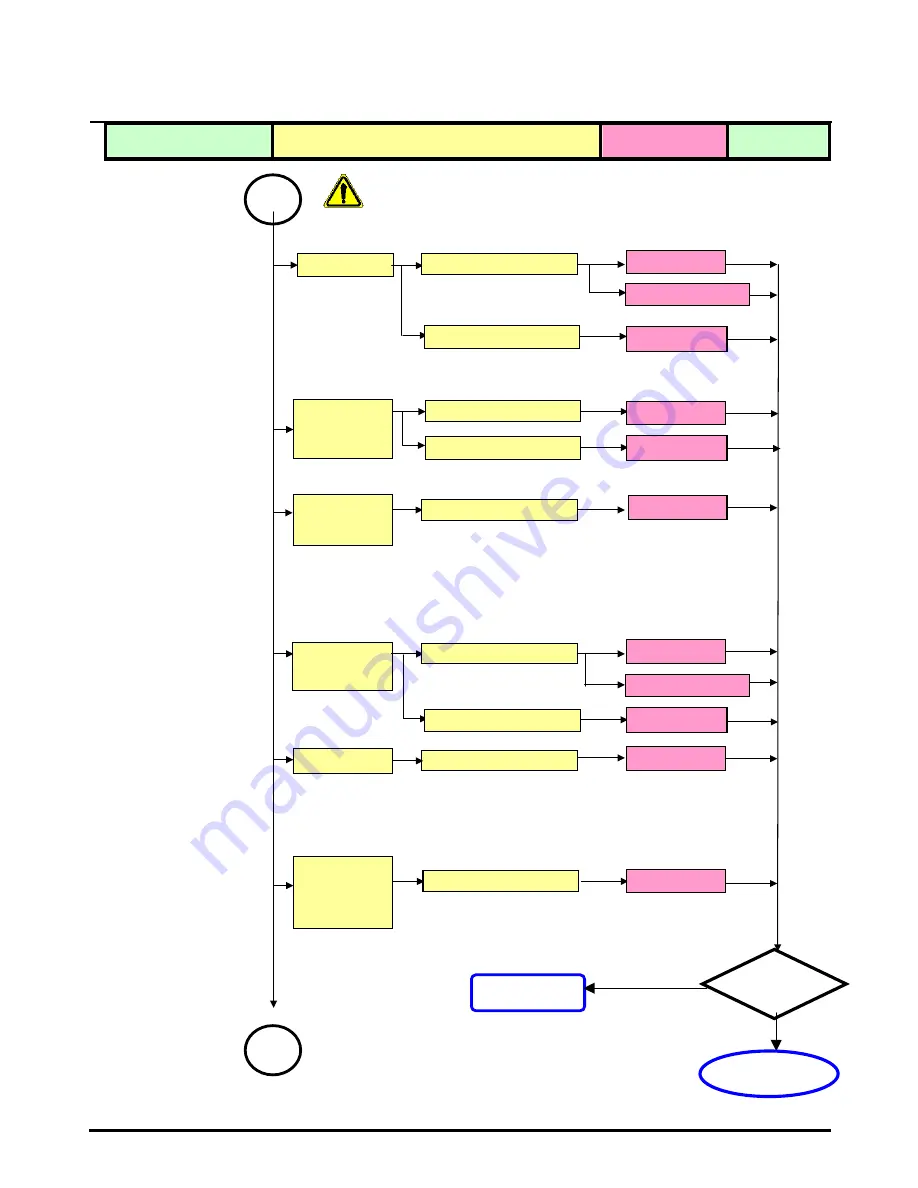
Defect Mode 

Failure Analysis 

Repair 

Testing 


Power on   
Display  
abnormal  

Check PCB

Check Panel

Gray value 
display             

R.G.B display 
abnormal  

Check PCB

Display Shut   
Down 

Check PCB

Check Panel

No signal 

Check PCB

Check PCB

Flicker 

Check PCB

Check OSD

※ 

“ Panel Change” Should be Performed to 

Level 3

 Repair stage 

Next Step

AD/B Change 

Inverter Change

Adjust VCOM 

AD/B Change 

Panel Change 

AD/B Change 

AD/B Change 

AD/B Change 

AD/B Change 

Inverter Change

Panel Change 

TEST 

NG 


Completed 

Содержание AL506

Страница 1: ...move FFC 22 6 4 Remove Bezel 22 6 5 Remove lnverter 23 6 6 Change New Inverter 26 6 7 Remove AD PCBA 29 6 8 Change New AD PCBA 32 6 9 Change New SW B PCB K 35 6 10 Change New SW B PCB K 36 6 11 Case Assembly 37 7 FRU 41 8 Method for LCD Monitor Testing after Servicing 43 8 1 Test Method Without Connection of Computer 43 8 2 Test Method with Connection of Computer 44 8 3 Definition of the Connector...

Страница 2: ...LCD monitor is plastic material and thin glass drop or sharp impact will cause damage to the LCD monitor 1 4 Do not use alcohol or ammonia based liquid to clean the monitor If necessary clean with a slightly damp cloth Disconnect the monitor from the power supply before cleaning 1 5 Remove the power supply immediately in case of abnormality occurred in the LCD especially strange noise of smell 1 6...

Страница 3: ...r Appearance Description 2 1 Front View Turbo Menu Contrast Button Exit Brightness Exit Volume Auto Auto Setup Power Switch Power Indicator Green Normal Blue Power Saving Orange Power Off Speakers 1 2 3 4 5 6 7 8 1 2 3 4 5 6 7 8 ...

Страница 4: ...ACER Monitor AL506 2 2 Rear View DC Power Jack DC In Stereo Mini Jack LINE IN D sub mini 15pin Connector D SUB Lock hole 10 13 12 11 13 12 11 10 ...

Страница 5: ...Monitor AL506 2 3 System Block Diagram Inverter Audio Amp A D converter DC DC converter LCD controller Scaler OSD T con LCD panel Speaker Lamp X3 Adapter IN 12VDC Power OSD Keypad Audio IN Analog IN Speaker ...

Страница 6: ... _SPEAKER_ CIRCLE_ASSY 2 OSD PCBA 3 PANEL ASSY 4 PET_FILM_METAL_ FRAM_REAR 5 SMART PCBA 6 INVERTER 7 FFC AD_OSD 8 PET ISOLUTION FILM 9 METAL COVER SMART 10 REAR_STAND_ W O_TUNER_ASSY 11 SEAT_ELLIPSE_ASSY 12 SCREW 13 SCREW 14 SCREW 15 STAND OFF 16 SCREW ...

Страница 7: ...8 3 PANEL ASSY 44A1513026 4 PET_FILM_METAL_FRAM_REAR 7341391001 5 SMART PCBA 35A15S0203 6 INVERTER 2714000001 7 FFC AD_OSD 3241500001 9 METAL COVER SMART 41A1599115 10 REAR_STAND_W O_TUNER_ASSY 40A1592966 11 SEAT_ELLIPSE_ASSY 40A1592949 12 SCREW 42A9930001 13 SCREW 42A9920002 14 SCREW 42A9930008 15 STAND OFF 42A9940007 16 SCREW 42A9930009 ...

Страница 8: ...the Buttons to make the appropriate adjustment or setting For example to correct for vertical position select Menu page number 1 and then press the Menu Button Then select V Position by using the Buttons An adjustment scale appears after you press the Menu Button Use the Buttons to change the vertical position settings The vertical position of the overall display should be changing accordingly whi...

Страница 9: ... other adjustments have only one setting which applies to all signal timings Adjust Menu contents Pressing or Menu buttons for the adjustment when the OSD is executed Menu 1 1 Adjust the Brightness when you are using the monitor in a dark room and feel the screen is too bright Note SWITCHING BRIGHTNESS CONTRAST ADJUSTMENT To switch between Brightness and Contrast adjustments press the Menu Button ...

Страница 10: ...e signal input is changed Color Temp Color 1 9300K Color 2 7500K Color 3 6500K sRGB User sRGB is an international standard which defines and unifies the difference of color appearance between equipment Sharpness Adjust the picture quality at resolutions of less than 1024 768 You can change the picture quality from 1 to 5 sharp to soft Press the Button to change the picture quality in numerical ord...

Страница 11: ... the overall display Press the Button to move the OSD in numerical order Press the Button to move the OSD in reverse numerical order Language Eng English Dth German Fns French Ity Italian Epl Spanish Jpn Japanese T C Tranditional Chinese S C Simplified Chines Return to Menu Language Volume Direct OSD Position Reset 3 1 5 4 2 ...

Страница 12: ...when the Menu is not displayed Volume Press the Volume Button when the Menu is not displayed When OSD menu is off holding this button for 1 2 seconds will switch the Mute function between ON and OFF Turbo Pct Picture Mode High brightness Text Text Mode Normal Eco Economy Brightness of back light is reduced Changing to a lower brightness mode can lessen eye fatigue Change from Picture Mode to Text ...

Страница 13: ...ols Definition Replacement of failed PCB and internal signal wire Tools 1 Multimeter 2 Electric screwdriver 3 Screwdrivers Testing equipment PC Electric screwdriver Torque value adjust to 1 5kgf cm Multimeter Computer for testing Screwdriver Hexagon Wrench ...

Страница 14: ... Dot Backlight Check PCB Check Panel Light Leakage Mura Image Sticking Brightness spot Particle Dot Defect Check Panel No display Check PCB Check Panel Noise Check PCB Check Panel Light On Test Next Step Panel Change Should be Performed to Level 3 Repair stage Panel Change AD B Change Panel Change AD B Change Panel Change Abnormal Display TEST NG A Completed ...

Страница 15: ...bnormal Check PCB Display Shut Down Check PCB Check Panel No signal Check PCB Check PCB Flicker Check PCB Check OSD Panel Change Should be Performed to Level 3 Repair stage Next Step AD B Change Inverter Change Adjust VCOM AD B Change Panel Change AD B Change AD B Change AD B Change AD B Change Inverter Change Panel Change TEST NG A Completed A ...

Страница 16: ...k Wire FFC Change Next Step Panel Change Should be Performed to Level 3 Repair stage Unavailable Check PCB Check Wire LED Dark LED Abnormal LED Flicker AD B Change AD B Change AD B Change SW B Change FFC Change FFC Change ON OF Abnormal LED display abnormal Abnormal Keyboard TEST NG Completed SW B Change SW B Change ...

Страница 17: ...ad Display Shut Down Check PCB Check Panel Display flicker tapping Check PCB Check Panel Next Step Panel Change Should be Performed at Level 3 Repair stage AD B Change AD B Change AD B Change Panel Change Abnormal BIOS OSD Other Abnormal Display TEST NG Completed Inverter Change Inverter Change ...

Страница 18: ...epair Testing Panel Change Should be Performed at Level 3 Repair stage Audio Abnormal Sound adjust abnormal Check PCB AD B change No sound Check speaker Check FFC Check PCB Speaker change FFC change AD B change Single sound SW B change TEST Completed ...

Страница 19: ...embly The flow of Monitor assembly and disassembly procedure as below Separate Stand Separate Cover Remove Inverter 1 2 3 Change Inverter Remove AD PCBA Change AD PCBA Cover Assembly Stand Assembly 4 5 6 7 8 Must to protect the Polarizar Scratch Must to protect ESD issue ...

Страница 20: ...ACER Monitor AL506 6 1 Remove Stand Bottom 6 2 Separate Cover Case Rear Assy Step 1 Press the hooks and remove the Seat Step 2 Completed Step 1 Rotate the Stand Hinge and lay it down ...

Страница 21: ...ACER Monitor AL506 Step 2 Loose Remove 5 screws Screw P N 42A99300009 Screwdriver 2 0 7mm Step 5 Completed Step 3 Remove Rear Case from Bezel Step 4 Lift up Rear Case ...

Страница 22: ...ACER Monitor AL506 6 3 Remove FFC 6 4 Remove Bezel Step 1 Pull out FFC from connectors at Switch Board and AD PCBA Step 2 Completed Step 1 Lift up LCD module and Remove Bezel Step 2 Completed ...

Страница 23: ... 6 5 Remove lnverter 6 5 1 Remove Metal Cover Step 1 Loosen Remove 2 Stand Off screws Stand Off Part No 42A9940007 Step 2 Loosen Remove the screw Screw Part No 42A9930008 Screwdriver 2 0 7mm Step 3 Loosen Remove 3 screws ...

Страница 24: ...ACER Monitor AL506 6 5 2 Remove 3 B L Wire Step 6 Completed Step 4 Open Separate Metal Cover PCB X with tool Step 5 Push Metal Cover AD Power PCB ...

Страница 25: ...itor AL506 6 5 3 Loosen Remove 3 Screws 6 5 4 Remove Inverter Step 1 Lift up Inverter slightly Step 2 Shift Inverter with care Separate its head from the housing at AD PCBA Step 3 Take Inverter apart Completed ...

Страница 26: ...CER Monitor AL506 6 6 Change New Inverter New Inverter Step 1 Shift Inverter with care plug its head into the housing at AD PCBA Step 2 Carefully lay down Inverter Step 3 Fasten 3 screws to fix inverter ...

Страница 27: ...ACER Monitor AL506 Step 6 Place Metal Cover PCB X Step 4 Insert Backlight wires Step 5 Place Metal Cover AD Power PCB Step 7 Push the metal Cover PCB X Forward to have the hook Latched ...

Страница 28: ...ACER Monitor AL506 Step 8 Fasten 3 screws Step 9 Fasten the screw Step 10 Fasten 2 Stand Off screws Step 11 Completed ...

Страница 29: ...emove AD PCBA 6 7 1 Remove Metal Cover SMART PCB X Step 1 Loosen Remove 2 Stand Off screws Stand Off Part No 42A9940007 Step 2 Loosen Remove the screw Screw Part No 42A9930008 Screwdriver 2 0 7mm Step 3 Loosen Remove 3 screws ...

Страница 30: ...ACER Monitor AL506 6 7 2 Remove AD PCBA Step 4 Open Separate Metal Cover PCB X Step 6 Completed Step 1 Remove the taps on X board FPC Step 5 Push Metal Cover AD Power PCB ...

Страница 31: ...ACER Monitor AL506 Step 2 Pull out the X Board FPC Step 3 Loosen Remove 4 screws Step 5 Take AD PCBA apart Step 4 Shift AD PCBA with care Separate its housing from head ...

Страница 32: ...ACER Monitor AL506 6 8 Change New AD PCBA Step 6 Completed AD PCBA Step 1 Place new AD PCBA Step 3 Fasten 4 screws Step 2 Shift AD PCBA with care join its housing with head at Inverter ...

Страница 33: ...ACER Monitor AL506 Step 4 Insert FPC to connector Step 6 Place Metal Cover PCB X Step 5 Place Metal Cover AD Power PCB Step 7 Push the metal Cover PCB X Forward to have the hook latched ...

Страница 34: ...ACER Monitor AL506 Step 10 Fasten 2 Stand Off screws Step 9 Fasten the screw Step 8 Fasten 3 screws Step 11 Completed ...

Страница 35: ...ACER Monitor AL506 6 9 Change New SW B PCB K Step 1 Separate both Audio Cables Step 3 Take SW B PCB K apart completed Step 2 Loosen Remove 2 screws Bezel Assy W AUDIO ...

Страница 36: ...ACER Monitor AL506 6 10 Change New SW B PCB K Step 1 Place new SW B PCB K Step 3 Insert Audio Cable to Connectors Step 2 Fasten 2 screws Step 4 Completed ...

Страница 37: ...ACER Monitor AL506 6 11 Case Assembly 6 11 1 Join Bezel with LCD module 6 11 2 Insert FFC Step 1 Insert both sides of FFC into connectors Step 1 Place LCD module Step 2 Completed Before Assembly ...

Страница 38: ...ACER Monitor AL506 6 11 3 Rear Case Assembly Step 1 Place Rear Case Step 2 Fasten 5 screws Step 4 Completed Before Assembly ...

Страница 39: ...ACER Monitor AL506 6 11 4 Stand Assembly Before Assembly Step 3 Completed Step 2 Place Seat Step 1 Rotate lift up Stand Hinge ...

Страница 40: ...ACER Monitor AL506 Step 3 Have the hook latched Step 4 Completed ...

Страница 41: ...1 T01 28A WG 180CM 50 L03VG 002 CABLES SIGNAL CABLE MONITOR CABLE A150X1 T01 30AWG 180CM 50 L03VG 003 CABLES POWER CORD 125V 3PIN US 27 L03VG 001 CABLES POWER CORD 250V 3PIN UK 27 L03VG 002 CABLES POWER CORD 3 PIN SWISS 27 L03VG 003 CABLES POWER CORD 3 PIN PRC 27 L03VG 004 CABLES POWER CORD 250V 3PIN EC 27 L03VG 005 CABLES POWER CORD 3PIN JAPAN 27 L03VG 006 CABLES POWER CORD 3PIN AUSTRIAL 27 L03VG...

Страница 42: ... 002 SCREWS FUNCTION BUTTON BOARD SCREW 86 L03VG 001 SCREWS BACK COVER SCREW 86 L03VG 002 SCREWS INVERTER MB SCREW 86 L03VG 003 SCREWS M B COVER SCREW 86 L03VG 004 SCREWS LCD BRACKET SCRWE 86 L03VG 005 SPEAKER SPEAKER LEFT 23 L03VG 001 SPEAKER SPEAKER RIGHT 23 L03VG 002 Notice The aforesaid specification will be changed without noticing Plz access to the website of http aicsl acer com tw spl for t...

Страница 43: ... 1 Method to start run in mode Step 1 Remove the VGA cable Step 2 Press the Auto simultaneously Step 1 White Step 2 Red Step 5 Black 2 seconds 2 seconds 2 seconds 2 seconds 2 seconds After exchange PCBA A D Inverter The Monitor should be performed run in for 4 hours Step 2 Red Step 5 Black Step 3 Green Step 4 Blue ...

Страница 44: ...puter 1 Connect the VGA cable of computer to the Monitor 2 Windows system environment test 8 3 Definition of the Connector Pin of Signal Cable Pin No 15 Pin side of signal cable Pin No 15 Pin side of signal cable 1 2 3 4 5 6 7 8 Red Green Blue NC Ground Ground red Ground green Ground blue 9 10 11 12 13 14 15 NC Ground NC SDA Horizontal synchronization Vertical synchronization SCL ...

Страница 45: ...ss 350 cd m2 Contrast Ratio 450 LCD panel Response Time Tr Tf 23 Tr 6 Tf 17 msec Separate Sync TTL Level Horizontal Sync Positive Negative Vertical Sync Positive Negative Graphic Input Connector D Sub mini 15 pins Power Input AC100 240 Worldwide V Power source Power Output 12 VDC Operation Mode 33 W Power consumption Power Saving Mode 3 W Tilt angle Upward Downward 30 0 degree Physical Dimension w...

Страница 46: ...Hz dot clock Audio d 3 5mm stereo mini jack 1 5W ch Horizontal Sync 28 63 kHz Synchronization Frequency Vertical Sync 55 78Hz Input Voltage AC100 240V Worldwide Frequency 50 60Hz Power Consumption 33W max Power Supply Power Management 3W max Lamp Type Cold Cathode Fluorescent Lamp Lamp Quantity 3pcs Backlight Lamp Life Time 40 000Hrs min Plug Play VESA DDC 1 2B Compliance Power Management VESA DPM...

Страница 47: ...tart Factory Mode 4 Then press the Buttons to switch between and 5 To run Auto Balance please have highlighted and press Menu bottom The screen will show the box as below 6 To run VCOM adjust please have highlighted and press Menu bottom Press the Button to make the appropriate adjustment or setting Time Date Year BIOS number AUTO F1 F2 F1 F2 ...

Страница 48: ...5014B001 inf 5 P15014B001 ini 9 2 Tools a ISP Kit Prepared by CMO refer fig 1 b RS232 Comport Cable Prepared by Agent ref fig 2 c D sub cable Original Assy d Adapter Original Assy 9 3 Install BIOS Software Simply way to ROM kit Please power off the monitor 9 3 1 Install BIOS FlashUpgraderNT exe Fig 1 Kit Fig 2 RS232 ...

Страница 49: ...ACER Monitor AL506 9 3 2 Kit equipped Step 1 Get a kit Step 2 Join R232 monitor cable and adapter Step 3 When the LED turns red it will start running Connect monitor Connect to adapter Connect PC ...

Страница 50: ...ACER Monitor AL506 9 4 Program Running Step 1 the indicated program Flash Upgrade NT exe ...

Страница 51: ...ACER Monitor AL506 Step 2 Do the following actions a Click the file b Choose COM1 or COM2 c Check Band Rate must be at 115200 Step 3 Click the bottom of Flash ...

Страница 52: ...ACER Monitor AL506 Step 4 Then it will show below box Step 5 a Power on monitor b After power on it will start flash rom ...

Страница 53: ...ACER Monitor AL506 Step 6 Notice of Flash completed ...

Страница 54: ...Item Term Description 1 OSD On Screen Display 2 H Position Horizontal Position 3 V Position Vertical Position 4 PCBA Printed Circuit Board Assembly 5 P B Power Board 6 B L Backlight 7 FPC Flat Cable 8 AD Board Analog to Digital Board ...

Отзывы: