


Acer M5 481/481G/481T/481TG System Utilities
2-9
NOTE:
NOTE
:
When prompted to enter password, three attempts are allowed before system halts.
Resetting BIOS password may require computer be returned to dealer.
Password on Boot
must be set to
Enabled
to activate password feature.
Passwords are not case sensitive.
A password must be alphanumeric (A-Z, a-z, 0-9), not longer than 12 characters.
Setting a Password
0
Perform the following to set a new user or supervisor password:
1.
Use the
and
keys to highlight the
Set Supervisor Password
parameter and press
Enter. The
Set Supervisor Password
dialog box is shown. (Figure 2-4)
NOTE:
NOTE
:
To change an existing password, refer to
Changing a Password
.
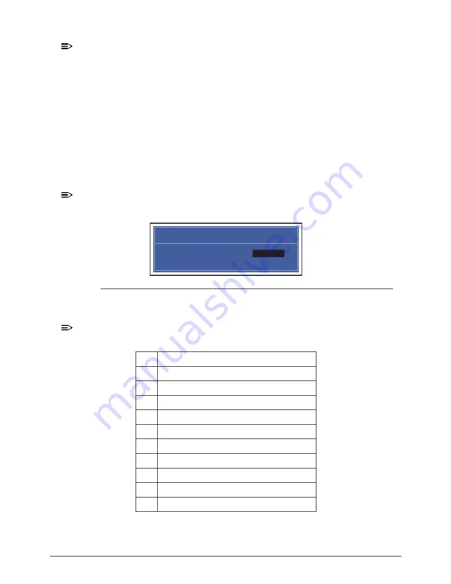
Figure 2-4.
Setting a Password: Set Supervisor Password
2.
Type a new password in the
Enter New Password
field and press Enter.
NOTE:
NOTE
:
The following characters may be used in a password:
IMPORTANT
:
+
Use care when typing a password. Characters do not appear on the screen.
A-Z
Alphabets A through Z (Not Case Sensitive)
0-9
Numerical Characters.
-
Dash
=
Equal Sign
[
Left Bracket
]
Right Bracket
.
Period
,
Comma
;
Semi-colon
/
Slash
\
Back-slash
Set Supervisor Password
Enter New Password [ ]
Enter New Password
Confirm New Password [ ]
Содержание Acer M5 481
Страница 1: ...Acer M5 481 481G 481T 481TG SERVICE GUIDE ...
Страница 8: ...viii ...
Страница 9: ...CHAPTER 1 Hardware Specifications ...
Страница 10: ...1 2 ...
Страница 54: ...1 44 Hardware Specifications and Configurations ...
Страница 55: ...CHAPTER 2 System Utilities ...
Страница 56: ...2 2 ...
Страница 73: ...Acer M5 481 481G 481T 481TG System Utilities 2 19 Figure 2 19 InsydeFlash ...
Страница 80: ...2 26 Acer M5 481 481G 481T 481TG System Utilities Figure 2 30 1394 GUID Number Menu Item 8 Press 0 to exit ...
Страница 83: ...CHAPTER 3 Maintenance Procedures ...
Страница 84: ...3 2 ...
Страница 91: ...3 9 Figure 3 2 Lower Cover Cabling ID Size Quantity Screw Type A M2 5x5 0 15 ...
Страница 95: ...3 13 ID Size Quantity Screw Type M2 5 x 1 x 7 Flat head 2 ...
Страница 97: ...3 15 Figure 3 2 Audio Board Screw Removal ID Size Quantity Screw Type M2 5 x 1 x 7 Flat head 4 ...
Страница 103: ...3 21 ID Size Quantity Screw Type M2 0 x 2 0 1 ...
Страница 105: ...3 23 ID Size Quantity Screw Type M2 0 x 2 0 1 ...
Страница 108: ...3 26 3 Remove LCD Module Figure 3 3 LVDS Cable Removal ID Size Quantity Screw Type A M2 5 x 2 5 2 B M2 5 x 2 5 3 ...
Страница 110: ...3 28 3 Remove battery pack NOTE NOTE Follow local regulations for battery disposal Figure 3 3 Battery Battery Removal ...
Страница 113: ...3 31 ID Size Quantity Screw Type A M2 0 x 2 0 2 B M2 0 x 2 0 2 ...
Страница 116: ...3 34 Figure 3 2 Fan Thermal Assembly Removal ...
Страница 118: ...3 36 ID Size Quantity Screw Type A M2 0 x 0 5 x 7 0 Flathead 3 B M2 0 x 0 5 x 7 0 Flathead 3 ...
Страница 122: ...3 40 ID Size Quantity Screw Type A M2 0 x 0 5 x 7 0 flathead 2 ...
Страница 130: ...3 48 Figure 3 3 ODD Module Installation ID Size Quantity Screw Type A M2x2 2 B M2 5x5 0 1 ODD Bottom ODD Bottom B ...
Страница 132: ...3 50 ID Size Quantity Screw Type A M2 5x5 0 15 ...
Страница 138: ...3 56 Figure 3 2 Audio Board Screws Removal ID Size Quantity Screw Type M2 0 x 3 0 2 ...
Страница 143: ...3 61 ID Size Quantity Screw Type M2 0 x 2 0 1 ...
Страница 146: ...3 64 Figure 3 3 Audio Board Screws Removal ID Size Quantity Screw Type A M2 5 x 2 5 2 B M2 5 x 2 5 3 ...
Страница 148: ...3 66 Figure 3 3 MIC Cable Positioning ...
Страница 153: ...3 71 Figure 3 2 Fan Thermal Screw Removal 1 3 2 4 5 6 ...
Страница 157: ...3 75 Figure 3 3 LCD Panel Insatllation ID Size Quantity Screw Type A M2 0 x 0 5 x 7 0 flathead 2 ...
Страница 159: ...3 77 Figure 3 3 LVDS Alignment ...
Страница 162: ...3 80 ID Size Quantity Screw Type M2 5 x 3 0 3 ...
Страница 166: ...CHAPTER 4 Troubleshooting ...
Страница 167: ...4 2 ...
Страница 172: ...Troubleshooting 4 7 LCD Failure 0 If the LCD fails perform the following Figure 1 3 LCD Failure ...
Страница 173: ...4 8 Troubleshooting Keyboard Failure 0 If the Keyboard fails perform the following Figure 1 4 Keyboard Failure ...
Страница 174: ...Troubleshooting 4 9 Touchpad Failure 0 If the Touchpad fails perform the following Figure 1 5 Touchpad Failure ...
Страница 188: ...CHAPTER 5 Jumper and Connector Locations ...
Страница 189: ...5 2 ...
Страница 191: ...5 4 ...
Страница 192: ...CHAPTER 6 FRU Field Replaceable Unit List ...
Страница 193: ...6 2 ...
Страница 206: ...CHAPTER 7 Model Definition and Configuration ...
Страница 207: ...7 2 ...
Страница 233: ...7 28 Model Definition and Configuration ...
Страница 234: ...CHAPTER 8 Test Compatible Components ...
Страница 235: ...8 2 ...
Страница 243: ...8 10 Test Compatible Components ...
Страница 244: ...CHAPTER 9 Online Support Information ...
Страница 245: ...9 2 ...
Страница 247: ...9 4 Online Support Information ...


