


E-8
TROUBLESHOOTING
If your monitor fails to operate functionally, it may
be possible to correct the problem by making simple
checks as follows:
Refer to the operation instructions for your computer/
video adapter to ensure that you have the correct signal
output source for the monitor. Ensure that the switches
on the video adapter are set correctly for operation
with this monitor.
If the above steps fail to correct the problem contact
your dealer for servicing by qualified service
personnel.
Please remember that the monitor should be returned
for servicing together with the power cord.
* NOTE:
You can easily distinguish if the problem
is on the monitor or on the computer by
using the monitor’s built-in selftest
function.
With the monitor power ON, disconnect
the signal cable from monitor. If you see a
“NO SIGNAL” image on the screen, the
monitor is functioning properly, and the
problem is with the PC side or signal cable.
Problem
Check & Adjust
Blank screen
(
*NOTE
)
·
·
·
Monitor power switch,
power cord, signal cable,
or connector
PC power switch
Brightness & contrast
controls
Display position
off-center
·
Vertical centering &
horizontal phase controls
Display too small
or too large
·
Vertical & horizontal size
controls
Display too bright
or too dim
·
Brightness & contrast
controls
SERVICING
Refer all servicing to qualified service personnel.
Serious shock hazards exist within the covers
of this monitor.
D o n o t o p e n t h e c o v e r s u n d e r a n y
circumstances- there are no user serviceable
parts inside.
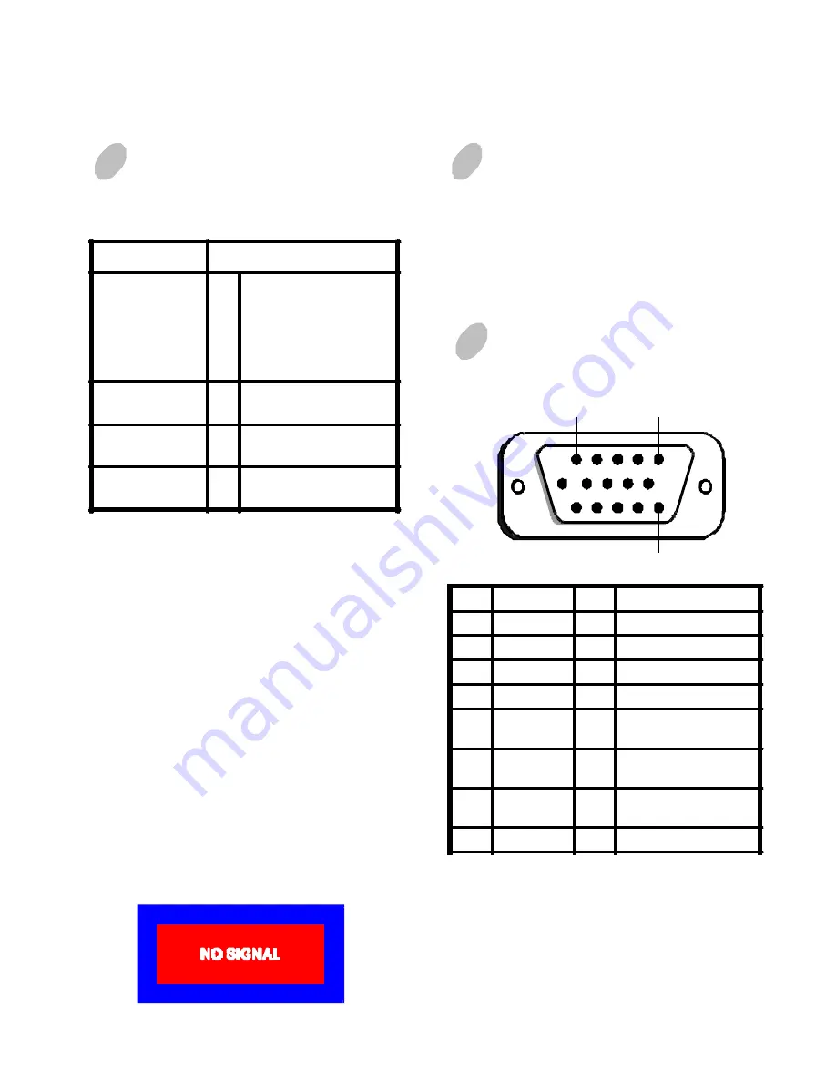
1
5
15
*NOTE:
This pin is used for self test detection; at
PC side, this pin has to be connected to
ground.
**NOTE:
This pin is used for PC99, at PC side, this
pin will 5VDC.
Pin
Function
Pin
Function
1
Red signal
9
** N O T E
2
Green signal
10
Digital ground
3
Blue signal
11
Ground
4
Ground
12
SDA (DDC2B)
5
*N O T
E
13
Horizontal
Synchronization
6
Red return
14
Vertical synchronization
& V C L K
7
Green
return
15
SCL (DDC 2B)
8
Blue return
SIGNAL CONNECTOR
INFORMATION


