3
Features of AcerHub 528B/528T
• Comply with IEEE 802.3 Ethernet 10BASE-T and 10BASE2 standards
• Compact size for desktop or wall mounting
• Plug and play, no configuration required
• 8 10Base-T (RJ-45) normal port for connection to workstations
• 1 uplink port for easy expanding to another hub or LAN switch
• 1 BNC port for trunk connection
• Per port Link and Partition LEDs for easy diagnostics
The AcerHub 528 Front Panel
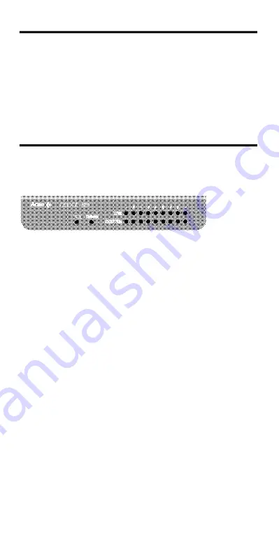
The following diagram illustrates the front panel of AcerHub 528. To dis-
tinguish model 528B or 528T, please see the label on the bottom side of
the hub.
1. PWR, the power (Green) Indicator
When the power LED is lit it indicates that the hub’s power is on.
2. Collision (ORANGE) Indicator
This LED indicator blinks when the hub detects a collision on the
network.
3. Link (GREEN) Indicators
These LEDs indicate the state of the data link of each port. The
LED will be
“ON” when the connection of that port is successful, and the LED
will be blinking when data is being received at that port.
4. Partition (ORANGE) Indicators
The LEDs will be “ON” when ports on the hub are been partitioned.
A port is partitioned if it experiences consecutive collisions. The
partitioned port is automatically isolated by the hub. The port will be
automatically recovered when the faulty condition disappeared.
When the port recovers, the partition LED returns to normal status
(“OFF”).


