


3-4
Service Guide
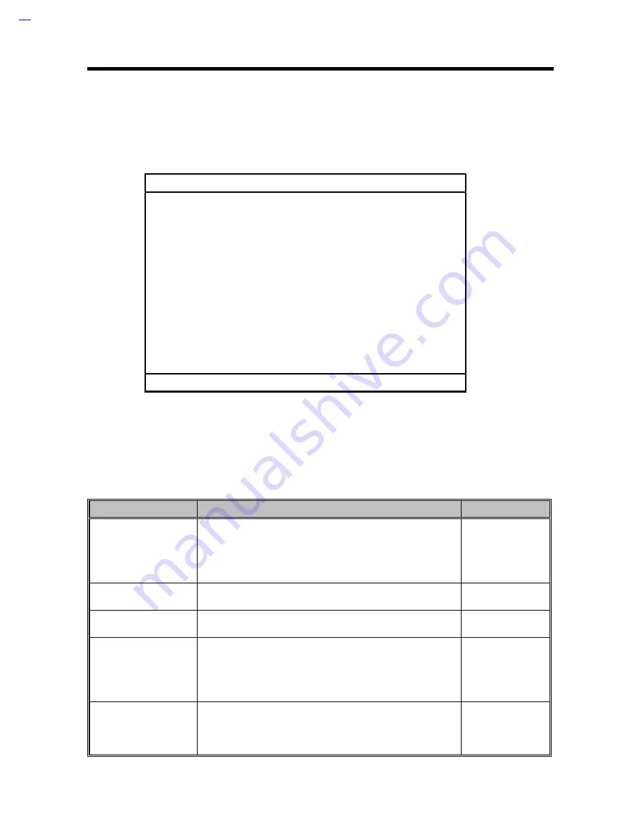
3.2 Startup Configuration
The Startup Configuration screen contains parameter items that are set-up when the computer
starts up.
Startup Configuration
Boot Display ---------------------------- [Auto]
Memory Test --------------------------- [Enabled]
Silent Boot ------------------------------ [Enabled]
System Boot Drive -------------------- [Drive A Then C]
Boot from CD-ROM ------------------- [Enabled]
Operating System --------------------- [Windows 95/DOS]
USB Function Support -------------- [Disabled]
↑↑↓↓
=Move Highlight Bar,
→
→←
←
=Change Setting, Esc=Exit
Press
↑↑
and
↓↓
to move the highlight bar; press
→
→
and
←
←
to change the setting of the highlighted
parameter. To exit this screen and return to the main screen, press Esc.
The following table describes the parameters in this screen. Settings in boldface are the default
and suggested parameter settings.
Table 3-2
Startup Configuration Parameters
Parameter
Description
Setting
Boot Display
Sets the display device (computer LCD and/or external
monitor) to use when the computer starts (boots) up.
When set to Auto, the computer outputs to the external
monitor if one is connected; otherwise, the computer
outputs to the LCD.
Auto
Both
Memory Test
Runs or skips the memory test.
Enabled
Disabled
Silent Boot
Hides or displays or hides the POST (Power On Self Test)
screen messages.
Enabled
Disabled
System Boot Drive
Sets the startup (boot) sequence of the drives in your
computer.
For example, when set to Drive A Then C, the computer
searches for a system (bootable) diskette in drive A first
before proceeding with drive C.
Drive A Then C
Drive C Then A
Drive C
Drive A
Boot from CD-ROM
Tells the computer to search for a bootable disc in the CD-
ROM drive and boot from that disc.
If the computer cannot find a bootable disc, it proceeds
according to the System Boot Drive parameter setting.
Enabled
Disabled
Содержание 390 Series
Страница 14: ...1 2 Service Guide 1 2 System Board Layout 1 2 1 Mainboard Figure 1 1 PCB No 96183 1A Mainboard Layout Top ...
Страница 15: ...System Introduction 1 3 Figure 1 2 PCB No 96183 1A Mainboard Layout Bottom ...
Страница 96: ...2 50 Service Guide 2 3 3 Pin Configuration Figure 2 4 FDC37C67 TQFP Pin Diagram ...
Страница 97: ...Major Chips Description 2 51 Figure 2 5 FDC37C67 QFP Pin Diagram ...
Страница 102: ...2 56 Service Guide 2 3 6 Block Diagram Figure 2 6 FDC37C67 Block Diagram ...
Страница 111: ...Major Chips Description 2 65 2 4 4 3 Bottom View BGA Ball Assignments Figure 2 8 65555 BGA Ball Assignments Bottom View ...
Страница 126: ...2 80 Service Guide 2 5 4 1 Functional Block Diagram Figure 2 10 M38813 Block Diagram ...
Страница 128: ...2 82 Service Guide 2 6 2 Pin Diagram Figure 2 11 YMF715 Block Diagram ...
Страница 168: ......
Страница 169: ......
Страница 170: ......
Страница 171: ......
Страница 172: ......
Страница 173: ......


