3
OPERATION
Your Ace Industrial Products machine is designed as a
source capture device, i.e., it is intended to eliminate
smoke and particulate at their point of origin. Keeping
this in mind, the machine should be operated in the
following manner:
Re-read the section on Safety Warnings & Cautions
before proceeding any further.
1. Place the machine on a flat, level surface. Pick a
location that will allow unrestricted flow of the
exhaust air to the atmosphere.
2. For units with wheels or casters, lock the wheels or
block the wheels.
3. Place the collection nozzle as close to the work as
practical without interfering with the operator.
Secure the nozzle if necessary.
4. Using the ON/OFF switch, turn the machine on.
Should the motor not start , or should the machine
make unusual noises, immediately turn the
machine off and seek a trained maintenance
personnel. Do not continue to use the unit.
5. Upon completion of the specific manufacturing or
welding operation, turn the machine off.
Continuous running of the unit will reduce the life
of the filter and the motor brushes as well as
increase utility cost.
6. When the "clogged" filter light indicates that the
filter is clogged, turn the machine off and remove
power cord from its power source.
See the section on installation and use the reverse
process to remove the dirty filters. Re-install the new
filter and reconnect the machine to its power source.
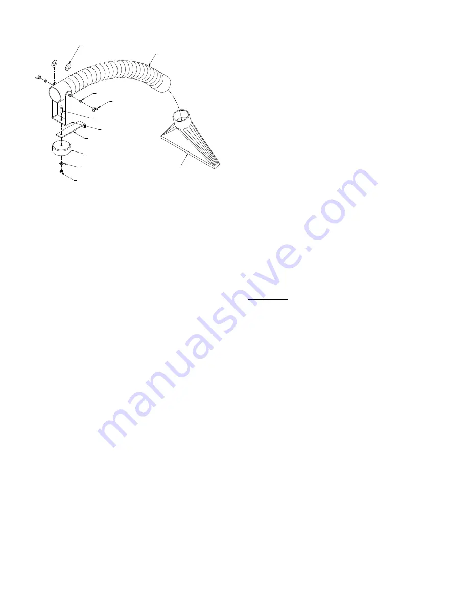
MAINTENANCE & REPLACEMENT PARTS:
WING NUT 1/4-20
(2 EA)
FLAT FIBER WASHER
(2 EA)
FLEX TUBE ASSY
(1 EA)
HEX HEAD BOLT 1/4-20 X 3/4
(1 EA)
SPLIT-LOCK WASHER 1/4"
(2 EA)
BRACKET HOSE SUPPORT
(1 EA)
SUPPORT LEG
(1 EA)
MAGNETIC BASE
(1 EA)
STEEL FLAT WASHER 1/4"
(1 EA)
HEX NUT 1/4-20 KEPS
(1 EA)
RECTANGULAR NOZZLE
(1 EA)
Figure 2
FILTER:
As previously stated in the "Theory of Operation"
section of this manual, the "clogged" filter indicator
light will light whenever the differential pressure across
the filter indicates that the filter is clogged. When
opening the unit, there are no vacuum hoses to
disconnect since the pressure sensing is accomplished
by measuring at the inlet and inside the suction
chamber. The differential pressure trip point is preset
and is not field adjustable.
When the filter gets dirty, it needs to be replaced with a
new one or the filter can be cleaned. To clean, take the
filter out of the unit and hold the filter 2 to 3 inches
above a concrete floor and drop the filter and rotate it
until most of the dirt falls out of the filter or the filter can
be vacuumed with a portable air vac (If needed, order
80-201MD). To re-assemble, use reverse process to
remove filter and sweep up dirt that is on the floor.
REPLACEMENT FILTER
Cartridge Filter ..................................................... 65250
MAINTENANCE:
WARNING:
MAINTENANCE ON THIS UNIT SHOULD
BE PERFORMED ONLY BY QUALIFIED, TRAINED
TECHNICIANS.
1. Motor Brushes- Motor brushes are available from
the company by ordering PART NUMBER 65007.
The use of high performance ball sleeve motors
provide about 500 hours of brush operation
(depending upon filter condition). Brushes should
be periodically checked after 500 hours use and if
worn, replace as a matter or preventative
maintenance.
2. Vacuum Motors- Motors are available from the
factory by ordering PART NUMBER 65001. These
motor are thermally protected by an automatic
reset thermal circuit breaker and will shut down if
they are overheated due to lack of air flow or
locked rotor condition.
DO NOT REPLACE THESE MOTORS WITH A
MOTOR THAT DOES NOT HAVE A THERMAL
OVERLOAD!


