background image


DS210_HardwareDocu_V1.50_EN.doc 

6 / 20 

4  Operation of the DS210 

Plug the power cord into the power supply pack. Plug the power cord into the power plug. Plug the low 
tension connector of the power supply pack into the plug socket at the back of the DS210 on the left side 
(see picture 2). The device is now ready for operation.  


NOTE 

Disconnection  of  the  equipment  from  the  line  voltage  is  done  by 
pulling the mains plug. 


4.1  Status LED of the DS210 

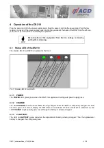
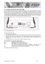
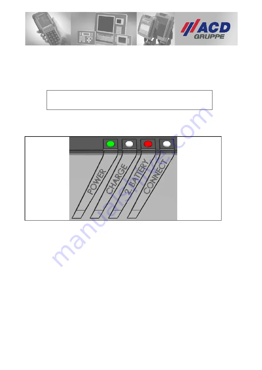
The status LED of the DS210 are placed at the front. 


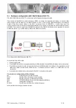
Pic. 1: Status LED of the DS210 


4.1.1  POWER 

The POWER LED glows green when the DS210 is supplied with voltage via power supply pack. 
 

4.1.2  CHARGE 

The LED CHARGE is red when the M210 is being charged. When the M210 is completely charged, the LED 
becomes  green.  For  correct  display,  the  M210  has  to  be  switched  off. When  the  M210  is  switched  on,  the 
LED CHARGE might possibly glow red, although the battery is already charged. 
 

4.1.3  2. BATTERY 

The  LED    2.  BATTERY  glows  red  when  the  replacement  battery  is  being  charged.  Then  the  replacement 
battery is charged, the LED glows green. 
 

Содержание DS210 Series

Страница 1: ...on Computertechnik Datentechnik Hardware Documentation DS210 Docking Station Version 1 50 Copyright ACD Gruppe Dieses Dokument darf ohne Zustimmung weder vervielf ltigt noch Dritten zug nglich gemacht...

Страница 2: ...0 7 4 3 Remove the M210 out of the docking station DS210 8 4 4 Data transfer via USB to a PC 8 4 5 Connection of a USB end device 8 4 6 Connection to the Ethernet optional interface 8 5 Hardware Confi...

Страница 3: ...esidential area is likely to cause interference in which case the user at his or her own expense will be required to take whatever measures may be required to correct the interference NOTE This equipm...

Страница 4: ...NTION For indoor use only ATTENTION The power pack must not be covered while it is in operation ATTENTION Do not place the device near heat sources e g fan heaters and do not expose it to direct sun b...

Страница 5: ...ply pack Country specific power cord 3 2 ACD DS210 Ethernet DS210 with Ethernet 10 100 Base T Power supply pack Country specific power cord CAT 5e FTP cable 3 3 ACD DS210 Modem 56K TTL DS210 with Anal...

Страница 6: ...f the DS210 The status LED of the DS210 are placed at the front Pic 1 Status LED of the DS210 4 1 1 POWER The POWER LED glows green when the DS210 is supplied with voltage via power supply pack 4 1 2...

Страница 7: ...At the DS210 ISDN this LED can be compared with the status LED at standard ISDN adapters The CONNECT LED glows when the ISDN adapter has established a physical connection with the ISDN conductor this...

Страница 8: ...e Connect LED does not check if the driver is being loaded it will show a connection in this case anyway 4 5 Connection of a USB end device USB end devices can be connected to the USB A connector of t...

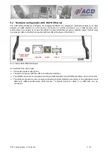
Страница 9: ...the connection of a USB end device e g a USB memory stick Pic 5 Back ACD DS210 Standard Connections from left to right Connection power supply pack The USB B connector is occupied according to USB Sta...

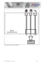
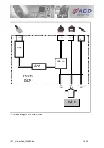
Страница 10: ...DS210_HardwareDocu_V1 50_EN doc 10 20 Pic 6 Block diagram ACD DS210 Standard USB Host USB Slave Power supply M210 USB B M210 USB A Con Po Su DS210 standard version...

Страница 11: ...erfore plug the network cable in the RJ45 connector with the LED at the back of the DS210 Pic 7 Back ACD DS210 Ethernet Connections from left to right Connection power supply pack The RJ45 connector w...

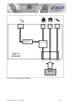
Страница 12: ...HardwareDocu_V1 50_EN doc 12 20 Pic 8 Block diagram ACD DS210 Ethernet USB Host USB Slave Voltage supply M210 USB B USB HUB USB Ethernet converter RJ45 with LED s M210 USB A Conn P S Netzteil DS210 Et...

Страница 13: ...d device e g a USB memory stick to the USB A connector Pic 9 Back ACD DS210 Modem 56K TTL Connections from left to right Power supply pack The USB B connector is occupied according to USB standard Usu...

Страница 14: ...reDocu_V1 50_EN doc 14 20 Pic 10 Block diagram ACD DS210 Modem 56K TTL USB B USB HUB USB Host M210 USB A Conn P S USB Slave Power supply M210 DS210 Analogue Modem USB serial converter analogue modem a...

Страница 15: ...k to the USB A connector Pic 11 ACD DS210 ISDN Connections from left to right Connection power supply pack The USB B connector is occupied according to USB standard Usual USB A B cables can be connect...

Страница 16: ...DS210_HardwareDocu_V1 50_EN doc 16 20 Pic 12 Block diagram ACD DS210 ISDN USB B USB HUB USB Host M210 USB A Conn P S USB Slave Power supply M210 DS210 ISDN USB serial converter ISDN adapter RJ45...

Страница 17: ...e a type B plug You can get such a cable directly from ACD Elektronik Article number 12100321 lenght of cable 1 8 m 6 2 Ethernet connection cable You can get a Ethernet connection cable directly from...

Страница 18: ...ensures a stable halt and the device cannot drop out of your hands during the cleaning process Please use a soft and wet cloth for cleaning ATTENTION Do not use corrosive chemicals cleaning lotions o...

Страница 19: ..._EN doc 19 20 8 Technical specifications Operating temperature 0 C 40 C 32 F 104 F Storage temperature 0 C 60 C 32 F 140 F Rel humidity 5 90 non condensable Input voltage power supply pack 90 264 VAC...

Страница 20: ...20 04 07 Changes Chapter 3 3 data transmission USB PC and 3 1 4 Connect 1 20 26 07 07 Minor changes 1 30 30 06 09 Insertation of chapter 4 3 Remove M210 out of the docking station DS210 Minor changes...

Отзывы: