background image

20

ACCU 1500

Operations

Operator’s Manual

5.1-1

5

Operation.

This chapter describes how to operate the computer
balancer in order to balance a wheel.
The standard balancing runs will be described first. In
chapter 5.4 and higher special modes and functions
will be described.

Be sure to be familiar with:
- possible dangers, refer to chapter 1
- the balancer, refer to chapter 4.

5.1

Mounting the wheel.

Clean the wheel thoroughly prior to mounting it to

the balancer.

No dirt should be left on the rim of the tire (excessive

dirt will effect the accuracy of the balance procedure)
.

Remove all weights from the rim.

Always balance a “clean” wheel!

Work safely. Wear safety glasses.

Use only clamping and centering devices that fit
properly on the balancer and are designed to be used
with it. In order to keep pace with technical progress,
the balancer, clamping and centering devices may
undergo design revisions. Always check for
compatibility between the devices and the balancer.
Refer to the supplied technical information.

The method used to mount a wheel depends on the
way the wheel is centered relative to the vehicle.
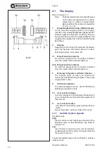
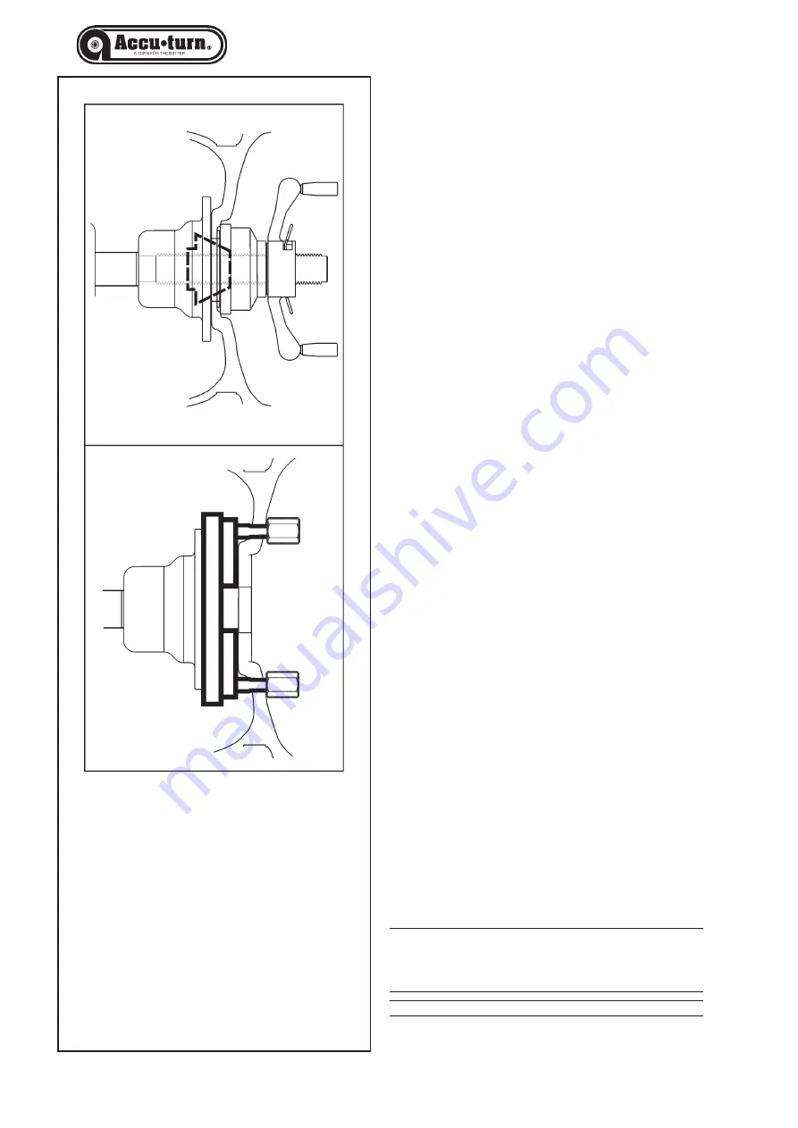
- When the rim has a true center hole, (a hub centric

wheel), use a cone. Refer to Figure 5.1-1, top. This
is also the faster way to mount a wheel. If the correct
cone is not available, or if a wheel is very hard to
balance, using an adapter flange may help.

- When the rim does not have a true center hole it

should be centered on the mounting holes (a lug
centric wheel), using an adapter plate.

- Refer to Figure 5.1-1, bottom.

Cone Mounting

Cone mounting is one of the most common ways to
mount automobile wheels. Choose the cone that fits
best when placed through the wheel center hole. Place
the cone and then the wheel on the shaft and ensure
that the cone centers the wheel when you tighten the
wing nut.

WARNING: ENSURE THAT THE WHEEL IS FIRMLY

AGAINST THE MOUNTING FLANGE AND THE
WING NUT THREADS ENGAGE 

AT LEAST

THREE TURNS ON THE SHAFT.

Содержание ACCU-TURN 1500

Страница 1: ...RN 1500 Rev C Digital Wheel Balancer OPERATOR S MANUAL SPARE PARTS EXPLODED VIEWS Machine à équilibrer MANUEL DE L OPÉRATEUR FIGURES PIECES DE RECHANGE Equilibradora MANUAL PARA EL OPERADOR TABLA DE REPUESTOS ...

Страница 2: ...lates was acquired increasesinanywaytheliabilitytothecustomer or to third parties TO THE READER While every effort has been made to ensure that the information contained in this manual is correct complete and up to date the right to change any part of this document at any time without prior notice is reserved Before installing maintaining or operating this unit please read this manual carefully pa...

Страница 3: ...et pré cautions de sécurité Toutes les informations figurant dans le présent manuel ont été fournies par le fabricant de l équipement VENCIMIENTO DE LA GARANTÍA Y LIMITACIONES DE RESPONSABILIDAD A pesar de que los autores han prestado la máxima atención al redactar este manual se señala que el contenido del mismo no altera en ningún modo las condiciones y los términos estándar acordados en la comp...

Страница 4: ... 40 5 3 2 3Motorcycle Dynamic Balancing Mode 40 5 3 2 4Static 1 balancing mode 42 5 3 2 5Static 2 balancing mode 42 5 3 2 6Motorcycle Static Balancing Mode 42 5 3 2 7PAX wheel balancing mode 42 5 3 2 8ALU Special mode HWM 44 5 3 3 Spinning the wheel 46 5 3 4 Weight application 48 5 3 5 Check spin 50 5 3 6 Results recalculation 50 5 4 Special modes 52 5 4 1 Minimization mode 52 5 4 2 Weight Unit To...

Страница 5: ...des C 69 8 Vente De La Machine 69 9 Annexes 69 Annexe Instructions pour l Installation 71 Figures Pieces de Rechange 81 1 Seguridad 7 1 1 Tipografía 7 2 Especificaciones 9 2 1 Condiciones 9 3 Introducción 11 3 1 Accesorios 13 4 Disposición 15 4 1 La Pantalla 17 4 1 1 Señales del sistema 17 4 2 El panel de entrada 19 5 Funcionamiento 21 5 1 Colocación de la rueda 21 5 1 1 Errores en el Montaje de l...

Страница 6: ...fic warnings and cautions when possible dangerous situations may be encountered during the procedures described 1 1 Format of this Manual This manual contains text styles which make you pay extra attention Note Suggestion or explanation CAUTION STRESSES THAT THE FOLLOWING ACTION MAY CAUSE DAMAGE TO THE UNIT OR OBJECTS ATTACHED TO IT WARNING STRESSES THAT THE FOLLOWING ACTION MAY CAUSE SEVERE INJUR...

Страница 7: ... SUIVANTE RISQUE DE CAUSER DES BLESSURES SERIEUSES AL OPERATEUR OU AUTRES Liste à puces Indique que l opérateur doit effectuer une action avant de pouvoir passer à l étape suivante de la séquence 1 Seguridad En el Folleto de Seguridad se describen todas las Precauciones de Seguridad relativas a la unidad consultar la Figura 1 1 Las Precauciones de Seguridad deberán ser entendidas totalmente por el...

Страница 8: ... Specifications Power Power Motor power Electrical consumption Fuses Protection class Measurements Cycle time wheel D 14 Speed of rotation range Offset Increments inches 10 mm Wheel dimensions Max width Max diameter Max weight Rim width Rim diameter NORMAL ALU STATIC Shaft and cones Shaft diameter Cone small Cone medium Cone large Dimensions Weight Shipment weight Dimensions h x d x l Shipment dim...

Страница 9: ... 10 mm Dimensions de roue Largeur max Diamètre max Poids max Largeur de la jante Diamètre de la jante NORMAL ALU STATIQUE Arbre et cônes Diamètre de bout d arbre Cône petit Cône moyen Cône grand Dimensions Poids Poids d expédition Dimensions HxDxL Dimensions d expédition Divers Niveau sonore 2 1 Conditions Lors d une utilisation ou un stockage prolongé les conditions ne doivent jamais dépasser Pla...

Страница 10: ...g surface of the wheel be clean and free of debris prior to mounting to the balancer Application The off the vehicle wheel balancer is designed for dynamic and static balancing of passenger car and light truck wheels that fall within the limits stated in the technical specifications This is a high accuracy measuring device Handle as you would any accurate measuring instrument Manuals to the unit T...

Страница 11: ...anuel utilisé par le personnel de maintenance seulement Instructions pour l installation Les instructions pour l Installation se trouvent au Ch 9 Annexes 3 Introducción Esta equilibradora de ruedas combina una tecnología avanzada y de alto rendimiento robustez y confianza con un funcionamiento sencillo y fácil de manejar La velocidad lenta de rotación de la rueda garantiza que esta equilibradora e...

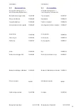
Страница 12: ... 10025517 10025516 14025821 10025415 525011 14007580 3 1 Accessories Refer to Figure 3 1 1 The standard accessories are Quick Release Hub Nut Spacer ring Universal drum Universal drum cushion Large cone Medium cone Small cone Stub shaft Shaft tightening stud User Calibration weight Weight pliers Caliper ...

Страница 13: ... Figure 3 1 1 Les accessoires standard sont Manivelle de serrage rapide Disque de distance Coupelle plastique Joint protection de la coupelle Grand cône Cône moyen Petit cône Arbre Embout de vissage arbre Masse de calibrage utilisateur Pince à masses Calibre largeur jantes 3 1 Accesorios Consultar lao Figura 3 1 1 Los accesorios normales son Tuerca rapida Espaciador Tambor Universal Amortiguador t...

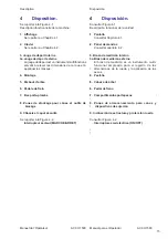
Страница 14: ... or accessories 9 Tilting frame and hood Refer to Figure 4 2 1 Mains switch ON OFF 4 Layout Refer to Figure 4 1 Functional description of the unit 1 Display Refer to Chapter 4 1 2 Input panel Refer to Chapter 4 2 3 Internal gauge arm 3a External gauge arm The gauge arms are a multi functional instruments used for measuring the dimensions of the rim and applying the weights 4 Flange 5 Stub shaft 6 ...

Страница 15: ...tar Figura 4 2 1 Interruptor General ON OFF 4 Disposition Se reporter à la Figure 4 1 Description fonctionnelle de la machine 1 Affichage Se reporter au Chapitre 4 1 2 Clavier Se reporter au Chapitre 4 2 3 Jauge de déport interne 3a Jauge de déport externe La jauge de déport est un instrument multifonctions servant à relever les dimensions de la roue et à appliquer les masses 4 Montage 5 Embout d ...

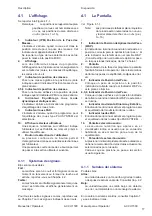
Страница 16: ...ow beep if an error is detected usually together with a system message indicating the nature of the error For all other audible beeps refer to Chapter 7 as these indicate errors 4 1 The display Refer to Figure 4 1 1 Note Positions related to the internal left plane of the wheel are labeled with a number followed by a while for external right plane positions the number is followed by b e g 1a 1b 1 ...

Страница 17: ... un error normalmente con un mensaje de sistema En cuanto a los demás sonidos consultar Capítulo 7 ya que indican errores 4 1 L affichage Se reporter à la Figure 4 1 1 Remarque Les positions se rapportant au plan gauche sur la roue sont numérotées avec un a les positions du plan droit avec un b par ex 1a 1b 1 Indicateur IPM Position de la Pose des Masses L indicateur s allume quand la roue est dan...

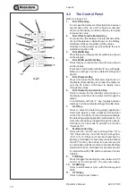
Страница 18: ...ugh the values 6 Rim Diameter and mm inch Key Press to reduce the rim diameter value shown on the display Hold down to rapidly scroll through the values In combination with the F key toggles between readings in inches default setting and millimeters 7 ALU Key Press to select the balancing weight application mode clip weight or tape weight and it s position on the rim The LEDs on the control panel ...

Страница 19: ...uche START démarrage Presser pour lancer la rotation de la roue après avoir abaissé le capot de sécurité 11 Touche STOP Presser pour arrêter la rotation de la roue 4 2 El panel de entrada Consultar la Figura 4 2 1 1 Tecla Distancia Llanta Sirve para incrementar el valor que aparece en la pantalla de la distancia entre el lado interno de la llanta y la cámara Mantener presionada la tecla para incre...

Страница 20: ... may undergo design revisions Always check for compatibility between the devices and the balancer Refer to the supplied technical information The method used to mount a wheel depends on the way the wheel is centered relative to the vehicle When the rim has a true center hole a hub centric wheel use a cone Refer to Figure 5 1 1 top This is also the faster way to mount a wheel If the correct cone is...

Отзывы: