background image

35

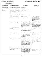
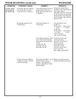
TROUBLESHOOTING (Continued)

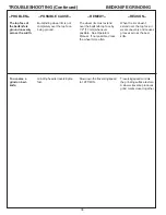
BEDKNIFE GRINDING

--POSSIBLE CAUSE--

--REMEDY--

--REASON--

--PROBLEM--

Direct coolant into the grinding
wheel, at the point of the grind.
See Operators Manual.

Take off about .002 to .003"
[.05 to .075mm] per pass
during rough grind.  See
Operators Manual.

Dress the wheel before the
finish-grinding pass on each
bedknife.  See Operators
Manual.

Dress the wheel before the
finish-grinding pass on each
bedknife.  See Operators
Manual.

Take off about .002 to .033"
[.05 to .075 mm] per pass
during rough grind.  See
Operators Manual.

Set the traversing speed to 12
FT/MIN.

Visually check the outside-
diameter run out while slowly
rotating the wheel.  Also check
the motor without a wheel
installed.  Replace the wheel if
out-of -round.

Loosen wheel flange and rotate
the wheel 90°.  Hand tighten
wheel flange and retry.  Repeat
process 3 times if necessary.

The top face of
the bedknife
shows burn
marks from being
too hot.

Grinding wheel is
glazing too
quickly.

Grinding motor
vibrates exces-
sively.

When the front face of the
bedknife gets too hot, the
steel loses its temper
(softens).

Too much stock removal in
one pass creates too much
heat and softens the steel.

Wheel will glaze if not
dressed often enough.
Also, as a general rule, use
a higher traverse speed for
the heavy grind.

Wheel will glaze if not
dressed often enough.  If
grinding wheel is not
extended 1/2" [12 mm] over
bedknife, it will glaze more
quickly because there is
less dressing.

Too light a grinding cut
doesn't permit enough
dressing action on the
wheel, so it glazes.

Too slow a traverse speed
can cause excessive heat
buildup in the grinding
wheel, which glazes the
wheel.

A grinding wheel which isn't
properly trued up on outside
or inside diameters can
vibrate excessively and
transfer that vibration to the
motor.

A--Coolant not directed onto
the bedknife and grinding
wheel.

B--Too heavy stock removal
during grinding.

C--Grinding wheel is glazing.

A--Wheel needs dressing.

B--Too light a cut when rough
grinding.

C--Grinding head is  traversing
too slow.

Grinding wheel is out of
balance.

Содержание 670

Страница 1: ...ATIC BEDKNIFE GRINDER ASSEMBLY AND SERVICE MANUAL WARNING You must thoroughly read and understand this manual before assembling or maintaining the equipment paying particular attention to the Warning Safety instructions 6707956 12 05 ...

Страница 2: ...lication and limitations as well as specific potential hazards 19 KEEP ALL SAFETY DECALS CLEAN AND LEGIBLE If safety decals become damaged or illegible for any reason replace immediately Refer to replacement parts illustrations in Service Manual for the proper location and part numbers of safety decals 20 DO NOT OPERATE THE GRINDER WHEN UNDER THE INFLUENCE OF DRUGS ALCOHOL OR MEDICATION 1 KEEP GUA...

Страница 3: ...inate dust or to maintain dust level below the Threshold Limit Value for nuisance dust as classified by OSHA IMPROPER USE OF GRINDING WHEEL MAY CAUSE BREAKAGE AND SERIOUS INJURY Grinding is a safe operation if the few basic rules listed below are followed These rules are based on material contained in the ANSI B7 1 Safety Code for Use Care and Protection of Abrasive Wheels For your safety we sugge...

Страница 4: ...e grinder Do not use a power washer to clean the machine CONTENTS Warnings Page 2 5 Contents and Specifications Page 4 Assembly Page 6 12 Maintenance Page 13 15 Adjustments Page 16 23 Troubleshooting Page 24 33 Electrical Schematic Page 34 Control Box Component I D Page 35 Parts List Page 36 49 SPECIFICATIONS Electrical Requirements 115V 50 60 Hz 15 amp circuit Net Weight 780 lbs 354 kg Shipping W...

Страница 5: ...ntact the manufacturer if necessary TORQUE REQUIREMENTS Throughout this manual we refer to torque requirements as firmly tighten or the like For more specific torque values refer to the information below Bolts Going into a Nut or Into a Thread Hole in Steel Refer to table at the right Bolts Going into a Thread Hole in Aluminum Use the Grade 2 values in the table at the right Socket Head Screws Use...

Страница 6: ... Be careful of the electrical wiring which was preconnected at the factory Install the Control Box Attach the control box to the right front end of the machine using the two 3 8 16 x 5 8 hex head bolts and two lock washers provided See FIG 1 The fasteners are shipped in an envelope inside the control box carton Remove the Grinder from the Pallet To remove the Grinder from the wood pallet 1 Unbolt ...

Страница 7: ...bellows will drain back into the coolant tray Place the level across the front and rear carriage rails near the right end of the carriage bed Level the right end in the same way as the left end For grinding accuracy the two ends must have the identical backward slant within 01 25 mm so the frame is not twisted Recheck the level in both directions When satisfactory tighten the hex jam nuts on the l...

Страница 8: ...ATING ON THE CIRCUIT DO NOT OPERATE THIS GRINDER WITH AN EXTENSION CORD The grinder is equipped with a low voltage relay which is factory preset at 100 VAC If the power supply line does not deliver 100 VAC power under load the relay will open and trip out the starter If this occurs your power supply line is inadequate and must be correct before proceeding further with the grinder PROPER GROUNDING ...

Страница 9: ...to a supply circuit protected by a properly sized circuit breaker or fuse SEE SERIAL NUMBER PLATE FOR FULL LOAD AMP RATING OF YOUR MACHINE Never modify the plug provided with the machine if it won t fit the outlet have a proper outlet and circuit installed by a qualified electrician ALWAYS PROVIDE A PROPER ELECTRICAL GROUND FOR YOUR MACHINE AN IMPROPER CONNECTION CAN CAUSE A DANGEROUS ELECTRICAL S...

Страница 10: ...seals from the actuator two screws each f Reinstall the drive shaft The right end of the shaft inside the coupling should be 1 8 1 4 3 to 6 5 mm from the end of the motor shaft See Fig 10A Retighten all set screws g Push the carriage back to the left and reattach the actuator with the mounting screw See FIG 9 3 Remove the two rail wiper brackets from each side of the carriage two screws each See F...

Страница 11: ...rts water to 1 part concentrate This will take about 3 25 gallons of water and 5 pints of concentrate 12 5 liters of water and 0 25 liter of concentrate Refer also to the label on the coolant container and the instructions packed with the Coolant Tank CHECK THE COOLANT PUMP Plug the pump motor cord from the top of the Tank to the female connector from the control box RISK OF ELECTRICAL SHOCK MAKE ...

Страница 12: ...s are not stretched NOTE If the unit doesn t begin a traverse cycle press the reset button on the motor contactor inside the control box See FIG 13 CHECK THE GRINDING MOTOR TurnallcontrolpanelswitchesOFF Closetheguarddoortoconnect the interlock Press START Press Grinding Motor Switch to ON Check that the grinding head runs properly Be prepared to press STOP if there is any problem NOTE If the grin...

Страница 13: ...r foam rail wipers FIG 15 every 6 months of operation Note Wipers are removed if optional bellows are installed 4 Clean the interior and the top cover of the Coolant Tank as necessary and at least every 6 months 5 Clean the exterior of the diamond dresser arm and spray with WD 40 or equivalent at least every 6 months 6 Clean the exterior of the grinding head hieght adjuster and spray with WD 40 or...

Страница 14: ...of the actuator bearings and the inner surface of the seals NOTE Because of the flood of lubricant you may find that the actuator slips and traversing is erratic or stalls This is not a problem as it will be corrected in Step 3 3 With a clean rag wipe the excess lubricant from the shafts Run the carriage back and forth through its range of travel and wipe the shafts after each traverse Repeat u nt...

Страница 15: ...inimized by using a mild automobile polish Three such products that tend to polish and fill scratches are Johnson paste Wax Novus Plastic Polish 1 and 2 and Mirror Glaze plastic polish M G M10 It is suggested that a test be made on a corner of the polycarbonate window with the product selected following the polish manufacturer s instructions Some Important DON TS DO NOT use abrasive or highly alka...

Страница 16: ...t of the way If the optional carriage bellows were installed the shaft seals may already have been removed 5 Remove the shoulder bolts holding the six bearings three on each side to the actuator block Remove the old bearings and discard them but save the inside washers and shoulder bolts Inspect the hole from which the bearing and shoulder bolt were removed for foreign matter Clean thoroughly 6 Wi...

Страница 17: ...not within specification Step 10 above adjust it 1 With the actuator bearings engaged to the drive shaft readjust the two outboard screws with springs that hold the actuator together To reach these screws you must remove the actuator bar assembly See FIG 17 Turn each outboard screw an equal amount when resetting Turn clockwise for more tension 2 Check the force again repeat Step 10 above Continue ...

Страница 18: ...lide the rails out of the bearings one at a time 4 Remove the three linear bearing pillow blocks and wiper brackets four screws each from the bottom of the car riage and discard the bearings 5 One at a time slide the three new linear bearing pillow blocks onto the carriage rails 6 Adjust the tension screw FIG 23 on the side of each bearing block so that when you radially rotate the pillow block ar...

Страница 19: ...cure the front pillow block Lift the front of the carriage and tighten the two inside pillow block screws Secure the front carriage rail to its V groove bosses with the six bolts 12 Recheck the bearing tension The tension is correct when you try to lift the carriage and can feel no free carriage move ment up or down Check for excessive carriage traverse load by using a spring scale to pull on the ...

Страница 20: ...ee Use a precision square held against the bearing shoulder and the rear rail as in FIG 26 TO ALIGN THE REAR RAIL AND DRIVE SHAFT The rear carriage rail and the drive shaft must be precisely aligned 1 Loosen the two bolts holding the bearing support blocks at each end of the drive shaft FIG 28 2 Align the drive shaft and rear carriage rail FIG 29 so the distance between their facing surfaces is 3 ...

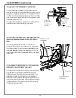
Страница 21: ...on the left and one adjustable on the right side To set the correct preload on the right side adjuster tighten the setscrew in FIG 34 until the spring is fully compressed solid then back off 1 2 turn TO ELIMINATE MOVEMENT IN THE DIAMOND DRESSER ADJUSTMENT COLLAR The adjustment collar on the diamond dresser See Fig 34 has a nylon ball and setscrew to put a holding drag on the diamond dresser shaft ...

Страница 22: ...ck nut if necessary D Tighten the setscrew holding the handwheel to the shaft Install and tighten the calibration ring setscrew 2 Check the nylon ball tension on the adjustment shaft threads at the grinding head slide See FIG 35A When you turn the handwheel there should be no free play in the handwheel before the grinding head slide moves If there is free play tighten the setscrew that pushes the ...

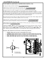
Страница 23: ...t at full CCW 8 30 Do not change this setting Left Traverse Reverse Acceleration Factory set at full CCW 8 30 Do not change this setting DB Dead Band is the potentiometer setting for the 50 or 60 Hz cycle control Factory set to 9 00 works for both 50 and 60 Hz Do not change this setting Calibrating the DWELL TIME rotary DIP switch adjusts the amount of time the process remains in the stop position...

Страница 24: ...r 115 Volts AC across starter coil A1 to A2 NOTE Contactor clicks when engaging Check for 115 voltAC between terminals T1 black and T3 white T1 and T3 are main power out lines NOTE T2 is jumpered to L3 Check reset overload on starter by pushing down on blue button Check terminal connections between contactor and overload relay If no voltage on output replace magnetic starter Check for 115 VAC at i...

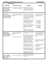
Страница 25: ...ad as above Check wire connections from the proximity switches and tighten down screws TROUBLESHOOTING Continued TRAVERSING POSSIBLE CAUSE REMEDY REASON PROBLEM Insufficient hesitation at carriage stops prior to reversing traverse direction for relief grinding If the carriage traverses to one end of stroke or the other and it stops and does not reverse direction If the carriage traverses past the ...

Страница 26: ...justment section of the manual Replace the lineal bearings in the main carriage Carriage should traverse freely with a 3 lb maximum loading Also check for excessive bearing preload For more detail see carriage bearing replacement in the adjustment section of the manual Check for 90 volt DC at the circuit board leads going to the motor Across terminals A1 and A2 check reading with a voltage meter W...

Страница 27: ...ot Full CCW Pot Full CW 0 VDC 9 75 VDC Pin 8 to 9 Pot Full CCW Pot Full CW 9 75 VDC 0 VDC If Yes pot is O K If No go to step below Check for 10 000 ohms red to white wires Full CCW 10 000 ohms Full CW 0 ohms Red to black wires Full CCW 0 ohms Full CW 10 000 ohms If Yes pot is O K If No replace potentiometer Minimum and maximum pot settings effect traverse speed Check potentiometer wiring for prope...

Страница 28: ...tight it causes excessive loading to drive the carriage When lineal actuator is disengaged the proper traverse load is 3 lb Use a tension scale to check A general guide only NOTE Check with linear actuator released When actuator spring tension is excessive bear ings will not rotate freely causing carriage to not run freely Wipe oil completely from shaft Spray down with WD 40 and wipe off Replace t...

Страница 29: ... that retain the shaft support blocks on each end of the actuator shaft Use a square to align bearing face 90 degrees to the front rail and holding the actuator shaft to the front rail to 3 375 dimension For more detail see align front rail and drive shaft in the adjustment section in the manual Turn the actuator screw clockwise 1 4 to 1 2 turn to release actuator from the drive shaft Slide the ca...

Страница 30: ...o B If the UPS is off turn it on With UPS on electromagnets work end of troubleshooting With UPS on electromagnets do not work check for 120VAC at the female receptacle at the back of the UPS If yes Go to C If No check continuity of cord 52 from MAG to UPS If bad replace cord If good replace or fully charge the UPS and retest Check for 12VAC at termials 71BD2 S and 66BD2 S If yes Go to E If no Go ...

Страница 31: ...Power must pass through the switch when pushed Power must pass through the cord and to the motor Check for 12 VDC at terminals 58MGTBL and 59MGTRD there is one set of terminals for each magnet If yes Call Factory Customer Service for assistance If no replace wires 58 and 59 Check for 120 VAC at terminal 65TF2BL and 64TF2BL If yes Go to B If no verify power is through the MAG If yes replace wire 64...

Страница 32: ... linear bearings are excessively noisy replace bearings See Page 19 Check straightness If not straight consult the factory through your distributor This is carefully checked at the factory so it is unlikely to be the cause Top face of bedknife is ground in a concave shape low in the center A loaded wheel creates undue pressure on the surface being ground Both ends of bedknife move because of this ...

Страница 33: ...helps maintain grinding straightness Uneven loading because of grit buildup in bearings can affect the straightness of grinding When grit buildup is excessive bearings may be noisy and must be replaced Straightness of rails is critical for accuracy of grinding Dress the wheel prescribed in the Operators Manual Follow the procedures in the Operators Manual On the final pass adjust only about 001 02...

Страница 34: ...the width Too coarse a grind on bed knife When the rim doesn t extend over the top face it wears unevenly and causes grooves across the bed knife Traversing speed controls the grinding surface texture A slower traverse produces grind marks closer together The wheel rim must extend over the bedknife top face by 1 2 13 mm whenever possible See Operators Manual If not possible dress the wheel more of...

Страница 35: ...wheel is glazing too quickly Grinding motor vibrates exces sively When the front face of the bedknife gets too hot the steel loses its temper softens Too much stock removal in one pass creates too much heat and softens the steel Wheel will glaze if not dressed often enough Also as a general rule use a higher traverse speed for the heavy grind Wheel will glaze if not dressed often enough If grindin...

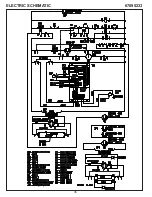
Страница 36: ...36 ELECTRIC SCHEMATIC 67095233 ...

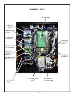
Страница 37: ...r Overload Relay Door Switch Relays Transformer for Electro Magnets Transformer for Actuator Bridge Diode for Actuator Circuit Breaker for Actuator 12 Amp Fulse for Electromagnets Bridge Diode for Electomagnets 2 Amp Fuse for Coolant Pump 1 Amp Start Circuit Fuse ...

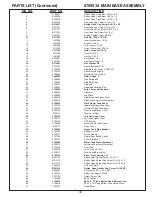
Страница 38: ...38 PARTS LIST 6709534 MAIN BASE ASSEMBLY ...

Страница 39: ...cknut Jam 10 24 Hex Nut 1 4 20 Thin Locknut 1 4 20 Nylon Locknut Jam 5 16 18 Nylon Locknut 5 16 18 Hex Nut 3 8 16 Hex Nut 1 2 13 Flat Washer 1 4 Split Lockwasher 1 4 Flat Washer 3 8 Split Lockwasher 3 8 Male Barb Connector 1 4509457 Plate Door Spring R H Warning Decal Safety Return Hose 1 Gas Spring 24 Stud Ball 10mm D Handle Adjustable Leveling Bolt Large Foley United Decal Grommet Leg Brace Righ...

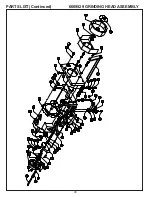
Страница 40: ...40 PARTS LIST Continued 6609529 GRINDING HEAD ASSEMBLY ...

Страница 41: ...702086 Diamond Dresser 23 3708121 Clamp Double Tube 24 3708543 Shoulder Bolt 25 3708553 Spring Compression 26 3708561 Adjustable Handle 27 3708657 Roller Dual Vee 28 3708658 Spring Compression 29 3709062 Washer Conical 30 3709304 Washer Thrust 31 3709526 Knob DIAGRAM NUMBER PART NUMBER PART DESCRIPTION 32 3708103 Washer Conical 33 3709705 Nylon Ball 34 3809047 Indicator Clear 35 6009023 Shaft Adju...

Страница 42: ...42 PARTS LIST Continued 6709531 TRAVERSE CARRIAGE ASSEMBLY ...

Страница 43: ...x 5 8 Hex Head Cap Screw 3 8 16 x 3 4 Hex Nut 1 4 20 Flat Washer 10 Split Lockwasher 10 Flat Washer 1 4 Split Lockwasher 1 4 Flat Washer 5 16 Split Lockwasher 5 16 Flat Washer 3 8 Split Lockwasher 3 8 Spacer 191ID x 438OD x 43L Compression Spring Grommet Shoulder Bolt 375D x 625L Warning Decal Release Actuator Warning Decal Hot Surface Wiper Seal Flexible Coupling Star Knob 5 16 18 Pillow Block Br...

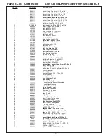
Страница 44: ...44 PARTS LIST Continued 6709533 BEDKNIFE SUPPORT ASSEMBLY ...

Страница 45: ... Pin 25D x 75LG Drive Lock Pin 25D x 875LG Roll Pin 25D x 1 125LG Flat Washer 5 16 Roll Pin 25D x 1 00LG Hex Nut 3 8 16 Nylon Locknut Jam 3 8 16 Nylon Hex Locknut 3 8 16 Nylon Locknut 1 2 13 thin Split Lockwasher 10 Flat Washer 1 4 Split Lockwasher 1 4 Split Lockwasher 3 8 Nylon Plug 3 16 Diameter Electromechanical Actuator Pivot Bearing Assembly T Knob 2 5 3 8 16F Handwheel 3 5 Diameter Compressi...

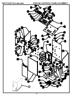
Страница 46: ...46 PARTS LIST Continued 6709536 CONTROL PANEL ASSEMBLY 50 ...

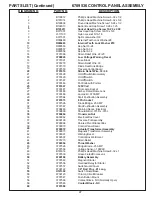
Страница 47: ... Cap Screw 3 8 16 x 5 8 Nylon Locknut 5 16 18 Split Lockwasher 3 8 External Teeth Lock Washer 8 Internal Teeth Lock Washer 10 Kep Nut 10 24 Kep Nut 6 32 Kep Nut 8 32 Strain Relief Wire 22 23 Low Voltage Warning Decal Fuse Block Strain Relief Wire 30 Diode Heat Sink Bridge Traverse Control Board Strain Relief Wire 33 36 On Off Switch Momentary On Off Switch On Off Switch Pot Knob with Pointer 120V ...

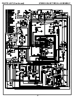
Страница 48: ...48 PARTS LIST Continued 6709536 ELECTRICAL ASSEMBLY ...

Страница 49: ... Overload Relay for Magnetic Starter Internal Tooth Lock Washer Fuse Block Wire Assembly STR FK W75 Fuse 1 AMP Slo Blo Wire Assembly 2 Loop W70 Wire Assembly 6FK 6FK W18 Right Hand Traverse Proximity Switch W38 Left Hand Traverse Proximitiy Switch W37 Wire Assembly 6FK 6FK W16 Wire Assembly 6FK 6FK W23 Wire Assembly 2 Loop W72 Kep Nut 10 24 Wire Assembly 25F 6FK W28 Wire Assembly 6FK 10RG W30 Wire...

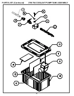
Страница 50: ...50 PARTS LIST Continued 3708784 COOLANT PUMP TANKASSEMBLY 15 ...

Страница 51: ... Cap Screw 5 K191501 10 Lockwasher Split 6 3709595 Shut Off Valve 7 3709593 Barbed Connector 8 3707532 Pump 115V 9 3708339 Connector Barbed Insert 10 3708725 Tank Coolant 11 3708774 Cover Coolant Tank 12 3708775 Divider Coolant Tank 5 13 3708778 Divider Coolant Tank 6 5 14 3708785 Instruction Sheet Coolant Tank 15 3389039 Coolant Hose DIAGRAM NUMBER PART NUMBER DESCRIPTION ...

Страница 52: ...52 ...

Отзывы: