


Description of Hardware
1-7
Status LEDs
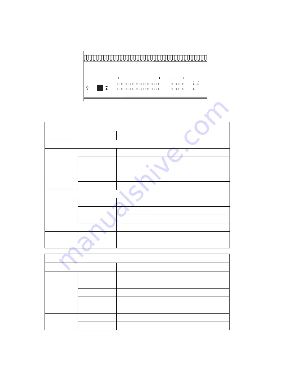
The LEDs, which are located on the VS2512A front panel for easy viewing, are
shown below and described in the following table.
Figure 1-5. Port and System LEDs
Port Status LEDs
LED
Condition
Status
VDSL Ports
Link
On Green
Port has a valid connection, port enabled
Flashing Amber
Port has a valid connection, port disabled
Off
Port does not have a valid connection
Activity
Flashing Green
Shows that traffic is crossing the port
Off
Shows that no traffic is crossing the port
Ethernet Ports
Link/Speed
On Amber
Port is operating at 1000 Mbps
On Green
Port is operating at 100 Mbps
Flashing Green
Port is operating at 10 Mbps
Flashing Amber
Port is disabled
Activity
Flashing Green
Shows that traffic is crossing the port
Off
Shows that no traffic is crossing the port
System Status LEDs
LED
Condition
Status
Power
On
Switch is receiving power
Diag
Flashing Green
System diagnostic test in progress
On Green
System diagnostic test successfully completed
On Amber
System diagnostic test failed
Stacking
On
Shows that the stacking link is connected
Master
On
The switch is the master switch in the stack
Off
The switch is a slave switch in the stack
Power
Stacking
Diag
Master
On
Off
2
3
4
5
6
7
8
9 10 11 12
VDSL
1
Activity
Link
Activity
Link/Speed
1
2
3
4
Ethernet
Содержание VM2524
Страница 1: ...VDSL Switch VS2512A VDSL Splitter VM2524 VDSL Splitter VM2548 Installation Guide...
Страница 2: ......
Страница 26: ...About the VDSL Switch VS2512A 1 14...
Страница 50: ...Cables B 6...
Страница 58: ...Specifications C 8...
Страница 59: ...Slide in Modules C 9...
Страница 60: ...Specifications C 10...
Страница 62: ...Ordering Information D 2...
Страница 69: ...Index Index 3 Web based management 1 3 Weighted Round Robin Queuing 1 4...
Страница 70: ...Index Index 4...
Страница 71: ......
Страница 72: ...VS2412A VM2524 VM2548 E072002 R01 150000010100A...


