


Quick Installation Guide
CheetaHub Power-3016G/3024G
2
3
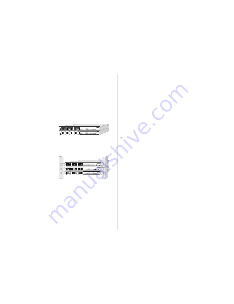
Mounting the Hub
These hubs can be placed directly on your desktop, or mounted in a rack.
Before you start installing the hub, make sure you can provide the right operating
environment, including power requirements, sufficient physical space, and proximity
to other network devices that are to be connected. Verify the following installation
requirements:
Power requirements: 100 to 240 VAC (± 10%) at 50 to 60 Hz (± 3Hz). The hub's
power supply automatically adjusts to the input voltage level.
The hub should be located in a cool dry place, with at least 10 cm. (4 in.) of space
at the front and back for ventilation.
Place the hub out of direct sunlight, and away from heat sources or areas with a
high amount of electromagnetic interference.
If you intend to mount the hub in a rack, make sure you have all the necessary
mounting screws, brackets, bolts and nuts, and the right tools.
Check if network cables and connectors needed for installation are available.
Stacking Hubs on a Flat Surface
These CheetaHubs can be stacked
anywhere there is a enough flat space,
such as on a table or desktop.
1. Stick the self-adhesive rubber foot pads (that come with this package) on each of
the 4 concave spaces located on the bottom of the first hub.
2. Place the first hub on a firm flat surface where you want to install the stack.
3. Repeat step 1 for each hub before stacking them. The rubber foot pads cushion
the hub against shock/vibrations and provide space between each hub for
ventilation.
Mounting Hubs in a Rack
Please comply with the following
instructions to ensure that your hub is
securely mounted in the rack.
1. Use a standard EIA 19-inch rack.
2. Use the brackets and screws
supplied in the rack mounting kit.
3. Use a cross-head screwdriver to attach the brackets to the side of the hub.
4. Position the hub in the rack by lining up the holes in the brackets with the
appropriate holes on the rack, and then use the supplied screws to mount the hub
in the rack.
Connecting the Hub System
These hubs have 16 (24) dual-speed RJ-45 station ports, one of which also serves
as a dual-speed MDI daisy-chain port.
Making a Connection via an RJ-45 Station Port
You can connect any RJ-45 (MDI-X) station port on the hub to any device that uses a
standard network interface such as a workstation or server, or to a network intercon-
nection device such as a bridge or router (depending on the port type implemented).
1. Prepare the devices you wish to network. Make sure you have installed 10BASE-T
or 100BASE-TX network interface cards for connecting to the hub's RJ-45 (MDI-X)
station ports.
2. You also need to prepare straight-through shielded or unshielded twisted-pair
cables with RJ-45 plugs at both ends. Use 100
Ω
Category 3, 4 or 5 cable for
standard 10 Mbps Ethernet connections, or 100
Ω
Category 5 cable for 100 Mbps
Fast Ethernet connections.
3. Connect one end of the cable to the RJ-45 port of the network interface card, and
the other end to any available (MDI-X) station port on the hub. The RJ-45 ports
support 10 Mbps and 100 Mbps Ethernet connections. When inserting an RJ-45
plug, be sure the tab on the plug clicks into position to ensure that it is properly
seated. Using a hub in a stand-alone configuration, you can network up to 16 (24)
end nodes.
I
Do not plug a phone jack connector into any RJ-45 port. This may damage the hub.
Use only twisted-pair cables with RJ-45 connectors that conform with FCC standards.
Notes:
1. Make sure each twisted-pair cable does not exceed 100 meters (328 feet).
2. We advise using Category 5 cable for all network connections to avoid any
confusion or inconvenience in the future when you upgrade attached devices
to Fast Ethernet.
Making a Connection via an MDI Daisy-Chain Port
To make a direct connection to another compatible hub or switch:
1. Prepare straight-through shielded or unshielded twisted-pair cables with RJ-45
plugs at both ends. Use 100
Ω
Category 3, 4 or 5 cable for standard 10 Mbps
Ethernet connections, or 100
Ω
Category 5 cable for 100 Mbps Fast Ethernet
connections.
2. Set the Port 1 daisy-chain switch to MDI and then connect to any MDI-X station
port on the other device. When inserting an RJ-45 plug, be sure the tab on the
plug clicks into position to ensure that it is properly seated.
Notes:
1. Make sure each twisted-pair cable does not exceed 100 meters (328 feet).
2. To connect to another hub or switch, you may also attach any RJ-45 MDI-X
port on the switch to an MDI daisy-chain port on the other device.
3. To connect to another hub or switch, you may also attach to (MDI-X) station
ports at both ends if you use crossover cabling.
Restrictions on Cascade Length
- When cascading to another repeater, note that
the attached repeaters will function as a single logical repeater, with all ports
attached to the same collision domain.
10 Mbps Cascade
- Based on the IEEE 802.3 recommendation, you may
cascade up to four 10 Mbps hubs.
100 Mbps Cascade
- When cascading to a Fast Ethernet hub, limit the daisy-
chain to two hubs. Another limitation for cascading Fast Ethernet concerns
connection length. All end-node devices (e.g., workstations or servers) must be
within 100 meters (328 feet) of the connected hub; and the overall length between
any two nodes should not exceed 205 meters (672 feet). The easiest way to
cascade two Fast Ethernet hubs is to connect the MDI daisy-chain port on the
front panel to an MDI-X port on the other hub. For example, if both node A and B
are linked to separate repeaters in a two hub system, each using 100 meters of
cable to connect to their respective hub, then the inter-hub cabling will be limited
to 5 meters (16 feet). The only way to extend the inter-hub cabling, would therefore
be to reduce the length of the cabling used to attach the end nodes to the hubs.
Ethernet Switch
- There are no formal restrictions on cascade length if a device is
connected to a switch, which effectively breaks up the collision domain. When a
collision domain is broken up by a device like a switch, cascade length is limited only
by the time-out requirements of the particular applications running over the network.


