HP module EVK hardware user guide – XM112, XB112
,
LH112
Page 27 of 41
2022-08-25
© 2018 by Acconeer – All rights reserved
Страница 1: ...HP module EVK hardware user guide XM112 XB112 LH112...
Страница 2: ...e EVK hardware user guide XM112 XB112 LH112 Page 2 of 41 2018 by Acconeer All rights reserved 2022 08 25 HP module EVK hardware user guide XM112 XB112 LH112 Author Acconeer Version 1 2 2022 08 25 Acco...
Страница 3: ...ematics 11 3 1 4 Bill of Material 15 3 1 5 Component Placement Drawing 17 3 1 6 Pinning Connectors 19 3 1 7 Buttons 22 3 2 HP Module 23 3 2 1 Overview 23 3 2 2 Electrical Schematics 25 3 2 3 Bill of M...
Страница 4: ...HP module EVK hardware user guide XM112 XB112 LH112 Page 4 of 41 2018 by Acconeer All rights reserved 2022 08 25...
Страница 5: ...n with integrated Baseband RF front end and Antenna In the HP Module The A111 sensor is integrated together with an M7 processor Atmel SAME70 which facilitates signal processing for advanced use cases...
Страница 6: ...1 Integration of radar functionality in your product to decrease development cost and time to market 2 Module evaluation and algorithm development in Python together with the Acconeer Python Explorat...
Страница 7: ...8V SPI external I2C UART 0 2 4 SWD MCU_INT MCU_GPIO ERASE NRST XB112 Board to board connector SPI internal 12MHz XTAL 5V 1 8V 1 8V FTDI FT230XS Misc GPIO pin header MCU_INT MCU_GPIO XM112 Board to boa...
Страница 8: ...is a breakout board designed for the XM112 Radar Module It makes the interfaces from the XM112 radar module accessible for evaluation and debug It also enables flashing of the XM112 via USB UART or S...
Страница 9: ...HP module EVK hardware user guide XM112 XB112 LH112 Page 9 of 41 2022 08 25 2018 by Acconeer All rights reserved Picture 2 shows the breakout board XB112 back side...
Страница 10: ...If no SPI data is needed the USB2 can be left unconnected USB1 must however always be connected If the USB UART interface is not used a dedicated USB charger can be inserted to USB1 When the power LE...
Страница 11: ...e EVK hardware user guide XM112 XB112 LH112 Page 11 of 41 2022 08 25 2018 by Acconeer All rights reserved 3 1 3 Electrical Schematics On the following pages please find the electrical schematics for t...
Страница 12: ...HP module EVK hardware user guide XM112 XB112 LH112 Page 12 of 41 2018 by Acconeer All rights reserved 2022 08 25...
Страница 13: ...HP module EVK hardware user guide XM112 XB112 LH112 Page 13 of 41 2022 08 25 2018 by Acconeer All rights reserved...
Страница 14: ...HP module EVK hardware user guide XM112 XB112 LH112 Page 14 of 41 2018 by Acconeer All rights reserved 2022 08 25...
Страница 15: ...F C23 470 NF K 10V X5R 1005 1 470nF C4 C5 47 PF J 50V C0G 1005 2 47pF C25 C26 8 PF C 50V NP0 C0G 1005 2 8pF C15 C17 C19 C21 C 34 1608 10 10V X5R 4 7uF 5 4 7uF R5 R7 R10 R11 R15 R20 R21 1005 J 0 7 0 Oh...
Страница 16: ...1 N A U5 FT4222H USB to SPI bridge 1 N A J5 J6 FTSH_105_04_F_DH SWD Connector Right angle 2x5 pin header 2 N A Manufacturer Samtech J7 J8 SWITCH TACTILE SPST NO 0 05A 12 434331045822 2 N A Manufacture...
Страница 17: ...ule EVK hardware user guide XM112 XB112 LH112 Page 17 of 41 2022 08 25 2018 by Acconeer All rights reserved 3 1 5 Component Placement Drawing The component placement drawing of XB112 is found below To...
Страница 18: ...HP module EVK hardware user guide XM112 XB112 LH112 Page 18 of 41 2018 by Acconeer All rights reserved 2022 08 25 Bottom Side...
Страница 19: ...UART USB1 is connected to the FTDI chip FT230XS which converts the UART interface from XM112 into USB signals The pinout of USB1 is shown in Table 2 The pinout of J1 Pin Number Signal 1 VBUS 2 D 3 D...
Страница 20: ...the 2x20 pin header are also available in the other connectors The pinout of the 2x20 pin header is shown in Table 4 Table 4 The pinout of J3 Pin Number Signal Pin Number Signal 1 NC 2 ERASE 3 GND 4 G...
Страница 21: ...TRACESWO 23 UART2_TXRX2 24 GND 25 UART2_RXTX2 26 SWDCLK 27 I2C_SDA 28 GND 29 I2C_SCL 30 MCU_INT 3 1 6 5 2x5 JTAG SWD pin header J5 The 2x5 JTAG SWD pin header 1 27mm pitch contains the signals needed...
Страница 22: ...ut of J6 Pin Number Signal Pin Number Signal 1 1 8V 2 I2C_SCL 3 MCU_INT 4 I2C_SDA 5 MCU_GPIO 6 UART4_TXRX2 7 UART2_RXTX2 8 UART4_RXTX2 9 UART2_TXRX2 10 GND 3 1 7 Buttons There are two buttons on the X...
Страница 23: ...XM112 XB112 LH112 Page 23 of 41 2022 08 25 2018 by Acconeer All rights reserved 3 2 HP Module 3 2 1 Overview The picture below shows the HP Module top side and Picture X shows the bottom side Picture...
Страница 24: ...HP module EVK hardware user guide XM112 XB112 LH112 Page 24 of 41 2018 by Acconeer All rights reserved 2022 08 25 Picture 2 shows the HP Module back side...
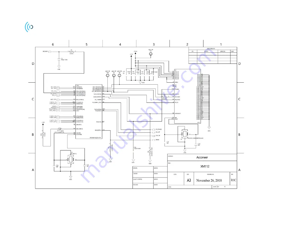
Страница 25: ...HP module EVK hardware user guide XM112 XB112 LH112 Page 25 of 41 2022 08 25 2018 Acconeer All rights reserved 3 2 2 Electrical Schematics Please find the electrical schematics of the XM112 below...
Страница 26: ...HP module EVK hardware user guide XM112 XB112 LH112 Page 26 of 41 2018 by Acconeer All rights reserved 2022 08 25...
Страница 27: ...HP module EVK hardware user guide XM112 XB112 LH112 Page 27 of 41 2022 08 25 2018 by Acconeer All rights reserved...
Страница 28: ...HP module EVK hardware user guide XM112 XB112 LH112 Page 28 of 41 2018 by Acconeer All rights reserved 2022 08 25...
Страница 29: ...X7R 1005 17 100nF C17 C18 C19 C20 8 PF C 50V NP0 C0G 1005 4 8pF C21 C24 1608 10 10V X5R 4 7uF 2 4 7uF R3 1005 J 0 1 0 Ohm R10 10 OHM F 1005 1 10 Ohm R8 30 OHM F 1005 1 30 Ohm R1 R2 1005 F 4 7K 2 4 7kO...
Страница 30: ...K hardware user guide XM112 XB112 LH112 Page 30 of 41 2018 by Acconeer All rights reserved 2022 08 25 3 2 4 Component Placement Drawing The component placement drawing of XM112 is found below Top side...
Страница 31: ...HP module EVK hardware user guide XM112 XB112 LH112 Page 31 of 41 2022 08 25 2018 by Acconeer All rights reserved...
Страница 32: ...PI_MISO 10 MCU_GPIO 11 GND 12 UART4_TXRX2 13 SPI_SS 14 UART4_RXTX2 15 GND 16 ERASE 17 UART0_TXRX3 18 SWD_NRST NRST 19 UART0_RXTX2 20 SWDIO 21 GND 22 TRACESWO 23 UART2_TXRX2 24 GND 25 UART2_RXTX2 26 SW...
Страница 33: ...d assembly The LH112 lens kit is delivered including four parts The included items are as shown in picture below 1 Lens and PCB holder 2 HBL Lens Hyperbolic Lens 3 FZP Lens Fresnel Zone Plate 4 Flat c...
Страница 34: ...Both lenses can be fitted in the holder in two different positions D1 or D2 The cover is only used in the D1 position The two positions will give you slightly different performance Performance result...
Страница 35: ...en mounted in front of the sensor the lenses affect the signal strength as well as the spread of the signal The expected performance for maximum gain and half power beam width HPBW can be found in the...
Страница 36: ...update In order to enter this boot mode the internal flash must be erased with the following sequence 1 Connect the XB112 together with XM112 to your PC with a micro USB cable to the USB1 Power UART0...
Страница 37: ...41 2022 08 25 2018 by Acconeer All rights reserved A progress dialog is shown showing the current progress When the flash is completed a new dialog is shown Press OK and exit the BOSSA application In...
Страница 38: ...8 of 41 2018 by Acconeer All rights reserved 2022 08 25 5 Safety 5 1 Electrostatic precautions Please take electrostatic precautions including using ground straps when using the EVK or any of its comp...
Страница 39: ...08 25 2018 by Acconeer All rights reserved 6 Regulatory Information Acconeer have no plans to certify the XM112 XB112 EVK it is only for evaluation purposes Regulatory Compliance for XM112 Refer to X...
Страница 40: ...112 XB112 LH112 Page 40 of 41 2018 by Acconeer All rights reserved 2022 08 25 7 Revision History Date Revision Changes 2018 12 19 1 0 Original version 2021 05 03 1 1 2022 08 25 1 2 ISO14001 updates Up...
Страница 41: ...or any failure to meet such industry standard requirements Unless explicitly stated herein this document Acconeer has not performed any regulatory conformity test It is the user s responsibility to as...